Rotation self-stopping convergent type rotary seal structure

A rotary sealing and anti-rotation technology, which is applied in the direction of engine sealing, engine components, mechanical equipment, etc., can solve problems such as increasing manufacturing costs, rotor vibration instability, and reducing sealing performance, so as to increase effective damping and Effects of effective stiffness, increased reverse swirl, and improved dynamic characteristics

Active Publication Date: 2017-07-14
XI AN JIAOTONG UNIV
View PDF7 Cites 18 Cited by
  • Summary
  • Abstract
  • Description
  • Claims
  • Application Information

AI Technical Summary

Problems solved by technology

This is mainly because the divergent sealing gap will produce negative effective stiffness, which will cause the critical speed of the rotor system to decrease; although the inlet anti-rotation plate and the anti-rotation jet can reduce the swirl velocity at the seal inlet, it will not affect the rotation of the seal rotor surface. The swirl vibration suppression effect of the seal chamber is limited (especially for the long seal of the shaft end of large turbomachinery), which cannot fundamentally improve the dynamic characteristics of the rotary seal rotor and solve the problem of rotor vibration instability
At the same time, the divergent sealing gap increases the leakage of the seal and reduces the sealing performance of the seal; the anti-swirl jet at the sealing inlet needs a separate high-pressure air source and channel, which makes the sealing structure complex and increases the manufacturing cost

Method used


Image

  • Rotation self-stopping convergent type rotary seal structure
  • Rotation self-stopping convergent type rotary seal structure
  • Rotation self-stopping convergent type rotary seal structure

Examples


Embodiment Construction

[0060] The present invention will be further described in detail below in conjunction with the accompanying drawings and technical principles.

[0061] Concrete structure of the present invention sees appendix figure 1 ~7, the design idea is as follows:

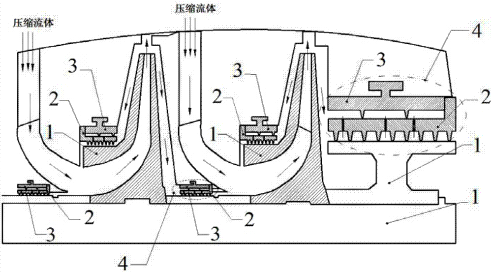
[0062] see figure 1 , the present invention provides a self-rotation-convergent rotary sealing structure, the rotary sealing structure 4 includes a stator outer ring 3 and a stator inner ring 2, the two are coaxially installed. The stator outer ring 3 of the rotary sealing structure 4 of the present invention can replace the traditional sealing structure and be installed at shaft ends, blade tops, partitions and interstages, etc., to enhance the stability of the rotor system. The stator inner ring 2 is installed on the stator outer ring 3 through bolts. The inner ring 2 of the stator and the rotating part 1 form the leakage channel of the working fluid.

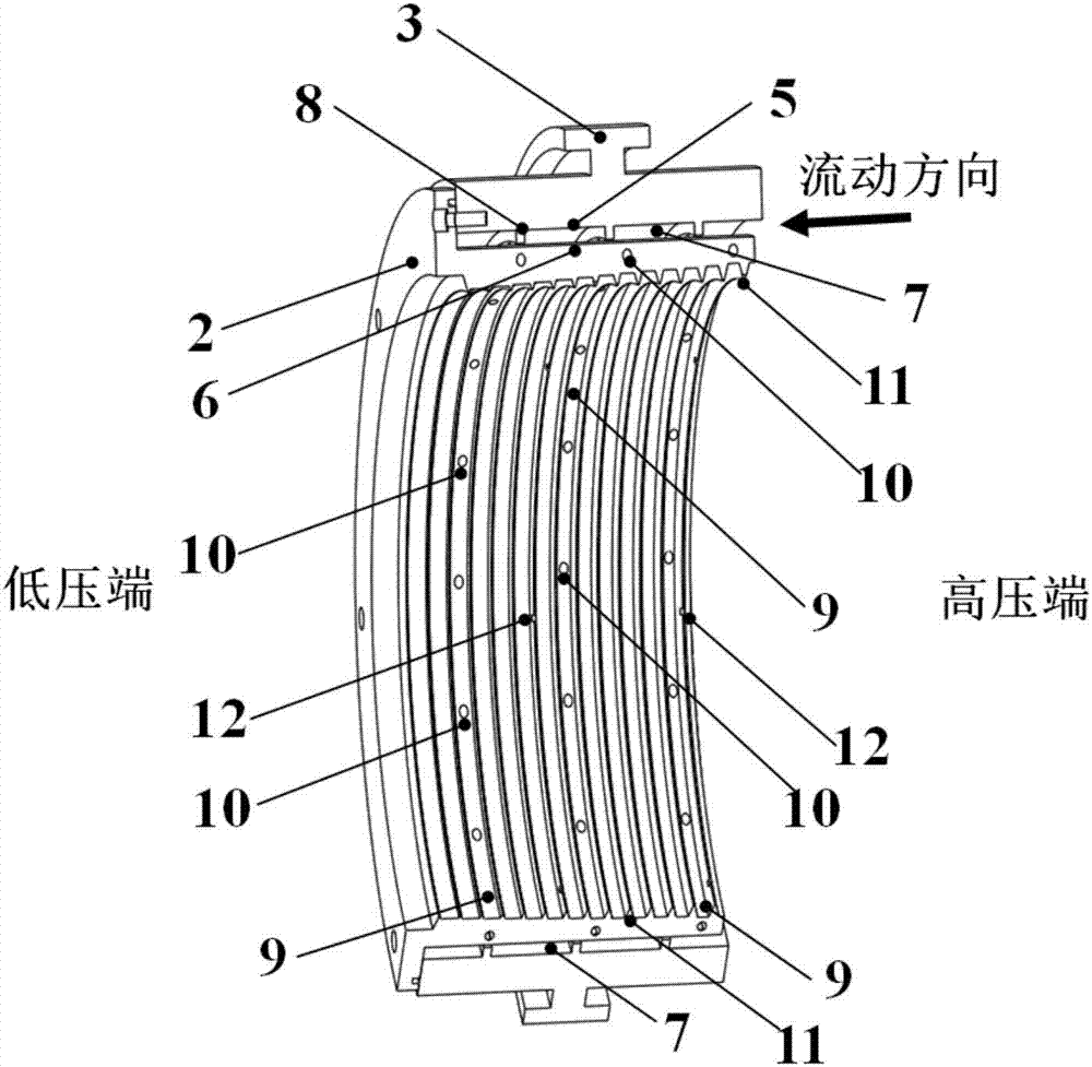
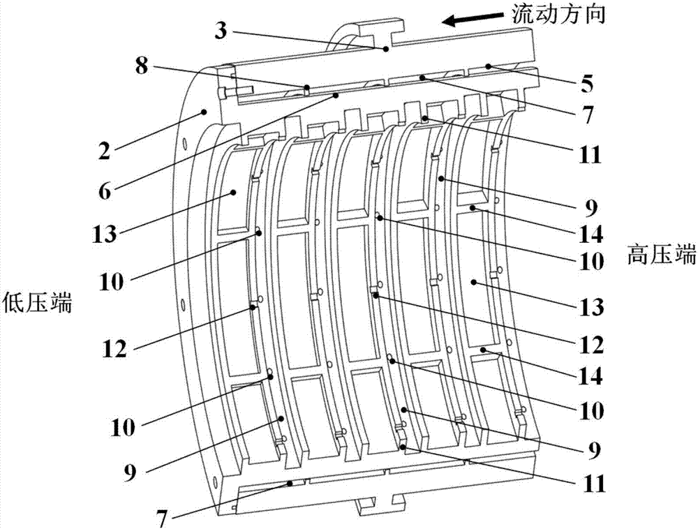
[0063] Referring to FIG. 2 , the stator outer ring 3 and the stator...


PUM


Abstract

The invention discloses a rotation self-stopping convergent type rotary seal structure. The rotation self-stopping convergent type rotary seal structure comprises a stator inner ring and a stator outer ring. A high-pressure rotation stopping cavity is formed between the inner surface of the stator outer ring and the outer surface of the stator inner ring, and a plurality of seal teeth are arranged on the inner surface of the stator outer ring. The stator inner ring is provided with low-pressure rotation stopping cavities and rotation stopping jet holes. The jet angle alpha of the rotation stopping jet holes is greater than or equal to 30 degrees but smaller than or equal to 60 degrees, and high-speed jet flow with the rotation direction opposite to that of a rotation component is formed inside the low-pressure rotation stopping cavities. The cavity depths of convergent type seal cavities in the structural forms of labyrinth annular cavities, bag type cavities, round hole cavities, hexagonal honeycomb cavities and the like in the stator inner ring are gradually decreased in the flowing direction. Upstream seal teeth of the seal cavities in the stator inner ring are provided with tooth crest grooves. Convergent type seal gaps between the seal cavities in the stator inner ring and the outer surface of the rotation component are linearly reduced in the flowing direction. According to the rotation self-stopping convergent type rotary seal structure, circumferential rotational flow in the seal cavities can be reduced effectively, effective damping and effective rigidity of the rotary seal are improved, and the static and dynamic stability of a rotor system is enhanced.

Description

[0001] Technical field: [0002] The invention relates to a rotary sealing structure, in particular to a self-spin-converging rotary sealing structure used in a turbomachinery rotor system, which has the functions of controlling leakage, suppressing vibration and increasing stability. [0003] Background technique: [0004] The working fluid leakage between the rotating parts and the stationary parts in turbomachinery is one of the main sources of loss. The rotary seal can control the leakage flow from the high-pressure area to the low-pressure area through the dynamic and static gap, effectively reducing the amount of leakage and the impact of the leakage flow. The effect of the mainstream has a significant effect on the operating efficiency of the turbomachinery. Currently commonly used rotary seal structures include labyrinth seals, honeycomb seals, hole seals, bag damper seals and brush seals. [0005] Although the rotary seal can reduce the leakage of dynamic and static g...

Claims


Application Information

Patent Timeline
Patent Type & Authority Applications(China)
IPC IPC(8): F16J15/44F16J15/447
CPCF16J15/164F16J15/444F16J15/4472
Inventor 李志刚李军
Owner XI AN JIAOTONG UNIV
Why Eureka
Try Eureka