A power management system and power management method

A power management system and power management technology, applied in battery circuit devices, current collectors, electric vehicles, etc., can solve the problems of difficult expansion, insufficient battery capacity, etc., to achieve capacity expansion, save capacity expansion costs, and ensure capacity and reliability. Effect

Active Publication Date: 2019-10-01
DONGGUAN MENTECH OPTICAL & MAGNETIC CO LTD
View PDF3 Cites 0 Cited by
  • Summary
  • Abstract
  • Description
  • Claims
  • Application Information

AI Technical Summary

Problems solved by technology

[0005] In view of this, the object of the present invention is to provide a power management system and power management method, which can effectively solve the problems of insufficient backup battery capacity and difficulty in convenient expansion in the communication power supply system.

Method used


Image

  • A power management system and power management method
  • A power management system and power management method
  • A power management system and power management method

Examples


Embodiment 1

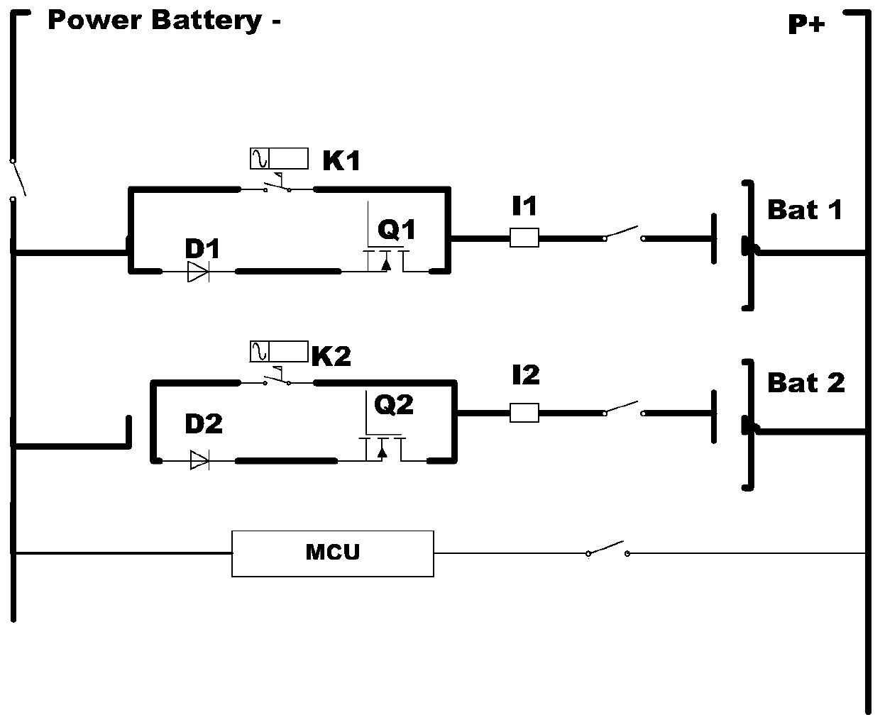
[0053] see figure 1 , this embodiment provides a power supply device, which includes a battery pack and an MCU; the battery pack includes two batteries Bat1 and Bat2 connected in parallel, which can be used as a main battery and a backup battery respectively.

[0054] On the parallel branch where each battery Bat1 / Bat2 is located, a battery switching device connected in series with the battery Bat1 / Bat2 is provided for charging or discharging the battery on this branch under the control of the MCU. The battery switching device includes a battery charging and discharging control unit and a current measurement unit connected in series; wherein, the battery charging and discharging unit includes a parallel mechanical switch K1 / K2 and an electronic switch Q1 / Q2, and a parallel branch where the electronic switch Q1 / Q2 is located is set There are Schottky diodes D1 / D2 connected in series with the electronic switches Q1 / Q2; the current measuring unit may specifically be a shunt I1 / I2...

Embodiment 2

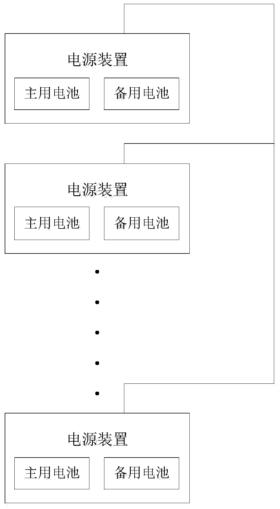
[0057] The embodiment of the present invention provides a power management system, which can not only satisfy the independent use of a single battery pack, realize battery management and capacity expansion, but also meet the parallel use of multiple battery packs. At any time, only the main battery or backup battery in a single battery pack is online, and the battery with better battery condition is used first, so that the final service life of multiple battery packs tends to be consistent.

[0058] The above-mentioned power management system includes several power supply devices connected in parallel, and a management unit for managing the several power supply devices.

[0059] power supply unit such as figure 1 and figure 2 As shown in the figure, it includes two battery channels, the main battery channel and the backup battery channel, and each battery channel is respectively connected to a lithium battery or a lead-acid battery. Each battery channel is provided with a m...

Embodiment 3

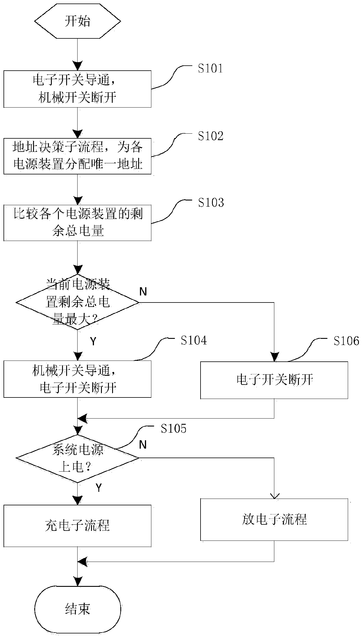
[0067] Based on the power management system provided in Embodiment 2, this Embodiment 3 provides a power management method to realize effective management of multiple sets of battery packs connected in parallel, such as image 3 shown, including the following steps:

[0068] Step S101 , after each power supply device is powered on, control the electronic switch of each power supply device to turn on and the relay switch to turn off, so as to ensure reliable power supply to the load.

[0069] Step S102, determine the address of each power supply device through the address decision sub-flow, ensure that the address of each power supply device is unique, and facilitate the switching cooperation between the parallel connected power supply devices and the reporting of status information.

[0070] Step S103, compare the remaining total power of each power supply unit (including the sum of the remaining capacity of the main battery and the backup battery in the power supply unit), se...


PUM


Abstract

The invention discloses a power supply management system and a power supply management method. The method comprises the steps that a system power supply is monitored in real time; when the system power supply is powered off, a power supply device currently having the maximum total residual power is selected out of multiple power supply devices and the power supply device is controlled to discharge, and the next power supply device having the maximum total residual power is switched on to perform discharging after the end of discharging of the current power supply device; and when the system power supply is powered on, the power supply device currently having the maximum total residual power is selected out of multiple power supply devices and the power supply device is charged, and the next power supply device having the maximum total residual power is switched on to perform charging after the end of power charging of the current power supply device. Capacity expanding of a DC power supply system can be effectively realized through parallel use of multiple sets of power supply devices, and multiple sets of low-capacity old batteries can be utilized so that the capacity expanding cost can be greatly saved and the service life of all sets of battery packs is ensured to be consistent.

Description

technical field [0001] The present invention relates to the technical field of power management, and more specifically, to a power management system and a power management method. Background technique [0002] Important precision electrical equipment such as communication equipment is mostly directly powered by DC, and its power comes from the AC power grid and is converted into stable and clean DC power through a rectifier. In order to ensure that the equipment can work continuously and uninterruptedly, the communication power supply system usually has a battery pack connected in parallel as the backup power supply or uninterruptible power supply of the base station, so as to prevent the equipment from being powered off when the AC power fails or fails. At present, most communication devices use lead-acid or iron-lithium batteries as backup power for base stations as uninterruptible power supplies. [0003] With the development of science and technology and the replacement...

Claims


Application Information

Patent Timeline
Patent Type & Authority Patents(China)
IPC IPC(8): H02J7/00
Inventor 汪崇
Owner DONGGUAN MENTECH OPTICAL & MAGNETIC CO LTD
Why Eureka
Try Eureka