Humidifier

A humidifier and atomizer technology, which is applied in air humidification systems, heating methods, lighting and heating equipment, etc., can solve the problems of inconvenient operation, low fogging efficiency, cumbersome water adding process, etc., and achieve convenient water adding and fogging efficiency. high effect

Active Publication Date: 2017-08-08
NINGBO JINTAO ELECTRONICS
View PDF9 Cites 0 Cited by
  • Summary
  • Abstract
  • Description
  • Claims
  • Application Information

AI Technical Summary

Problems solved by technology

It can be seen that the entire water adding process mentioned above is very cumbersome, and the water tank is heavy after being filled with water, and the operation is very inconvenient
[0004] For this reason, top-filling humidifiers have been launched on the market. Before using the top-filling humidifiers, water can be added directly from the water-filling cover provided on the upper part of the water tank without disassembling the water tank. The operation of adding water from the bottom is convenient and easy to use; but In this way, the air outlet must be placed upwards, resulting in low fog efficiency and small fog output.

Method used


Image

  • Humidifier
  • Humidifier
  • Humidifier

Examples


Embodiment 1

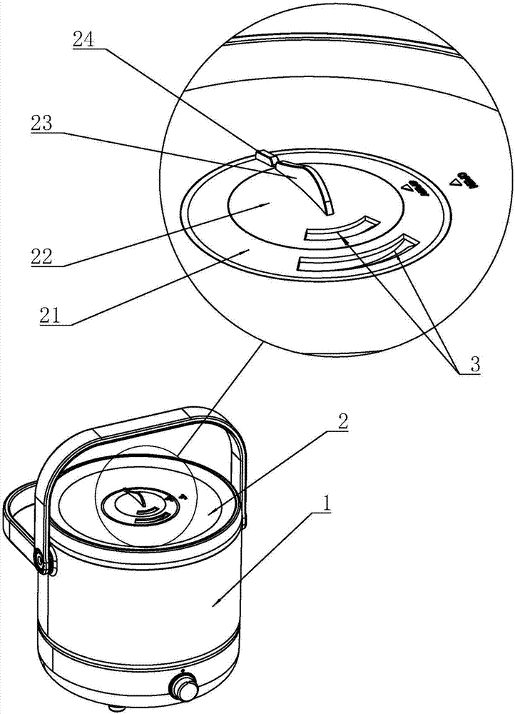
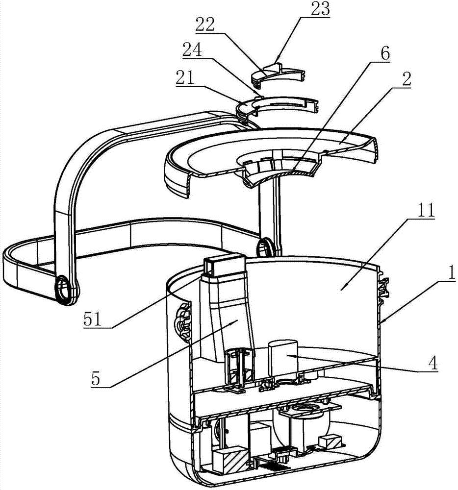
[0036] Embodiment 1: a kind of humidifier, such as figure 1 and 2 As shown, it includes a water tank 1 and a cover body 2. The inner cavity of the water tank 1 is a mist chamber 11; the bottom of the inner cavity of the water tank 1 is provided with an ultrasonic atomizer 4; A mist outlet 3 communicating with the inner cavity of the water tank 1 is provided; an air supply mechanism 5 is provided on the water tank 1, and the air outlet 51 of the air supply mechanism 5 is arranged on the side wall of the inner cavity of the water tank 1, and is tangential to the water tank 1 There are two air outlets 51 on the inner wall; in this way, after the airflow comes out of the air outlet 51, two circulations are formed, and then they are opposed at the positions around the half circle, so that the airflows at all positions in the circumferential direction are gathered in the middle, forming a large circle. Large air flow area to drive water mist to spray out; in addition, a guide plate...

Embodiment 2

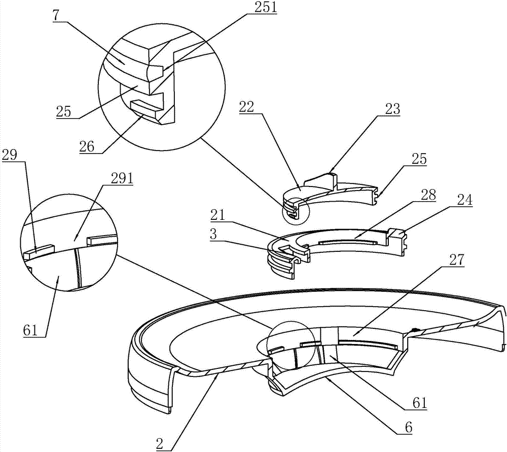
[0041] Embodiment 2: as Figure 4As shown, the difference from Embodiment 1 is that the top of the retaining ring 29 is provided with a stopper 8 that blocks the notch in the axial direction of the accommodating groove, and the receiving portion 25 abuts when the retaining tooth 26 is below the retaining ring 29. It is connected to the axial surface of the anti-off part 8; a bridge-shaped spring piece 9 is arranged between the retaining ring 29 and the anti-off part 8; and a waterproof coating is arranged on the spring piece 9.

[0042] When loading, the gear 26 abuts against the gear ring 29 first, then rotates the gear 26 to make it fall into the gap 291, continues to move down, and rotates again, so that even if the gear 26 is adjusted in the process of adjusting the mist outlet 3 Just right at the position of the gap 291, even if it is subjected to the mist top cover or external force at this time, the two screw caps are not easy to fall off.


PUM


Abstract

The invention discloses a humidifier. The humidifier comprises a water tank and a cover body. An ultrasonic nebulizer is arranged at the bottom of an inner cavity of the water tank. An air supply mechanism is arranged on the water tank, and air outlets of the air supply mechanism are horizontally formed in the side wall of the inner cavity of the water tank. The cover body is connected to the top of the water tank in a sleeving mode. The cover body is provided with mist outlets communicating with the inner cavity of the water tank, and a guide plate used for guiding air to go out is arranged below the mist outlets. The humidifier has the advantages that water can be added conveniently and quickly, the mist outlet efficiency is high, the double mist outlets are available, and the angles of the two mist outlets can be adjusted at will.

Description

technical field [0001] The invention relates to the field of indoor humidity adjustment equipment, in particular to a humidifier. Background technique [0002] With the development of science and technology, people's living standards are improving day by day, and people's requirements for living environment are gradually increasing. Among them, air humidity is one of the important factors affecting comfort, especially in northern China and places where air conditioners are used for a long time, the environment is very dry, and corresponding equipment should be used to increase the humidity of the air to adjust a comfortable living environment. Therefore, humidification equipment is more and more popular with families and has become a must-have small household appliance in the home. [0003] Humidifiers currently on the market are generally composed of a water tank and a mist generating chamber. Humidifiers are generally of the bottom-fill type, and the water-fill port and t...

Claims


Application Information

Patent Timeline
Patent Type & Authority Applications(China)
IPC IPC(8): F24F6/12
CPCF24F6/12Y02B30/70
Inventor 吴金潮
Owner NINGBO JINTAO ELECTRONICS
Why Eureka
Try Eureka