Disinfection water tank for AES antibacterial protection channel

A water tank and channel technology, applied in the field of disinfection water tanks for AES antibacterial protection channels, can solve the problems of increasing control equipment investment, reducing fogging effect, increasing production cost, etc., so as to improve fogging efficiency, improve fogging effect, and avoid loss. Effect

Pending Publication Date: 2022-03-11
安徽同净枫翎新材料科技有限公司 +1
View PDF6 Cites 0 Cited by
  • Summary
  • Abstract
  • Description
  • Claims
  • Application Information

AI Technical Summary

Problems solved by technology

[0003] In order to increase the atomization effect, the existing disinfection water tank chooses an ultrasonic atomizer for atomization operation, but when the depth of the liquid level is too high, the effect of fog generation will be reduced, or even no fog will be generated, which requires strict control of the position of the atomizer In the prior art, the control device is used to repeatedly pump the detoxified water for atomization, which is troublesome to operate, and increases the input of control equipment and increases the production cost.

Method used


Image

  • Disinfection water tank for AES antibacterial protection channel
  • Disinfection water tank for AES antibacterial protection channel
  • Disinfection water tank for AES antibacterial protection channel

Examples


Embodiment 1

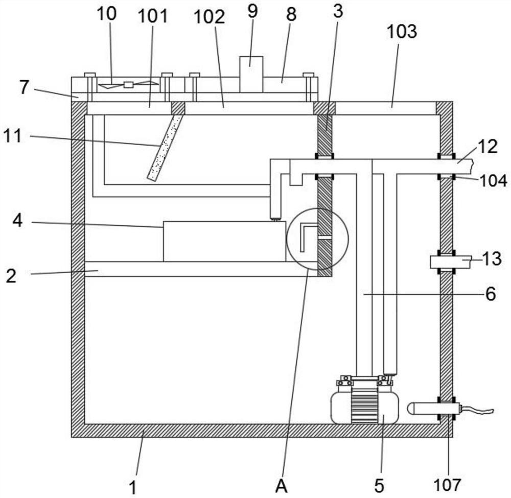
[0032] Such as Figure 1-3 As shown, a disinfection water tank for an AES antibacterial protection channel, including

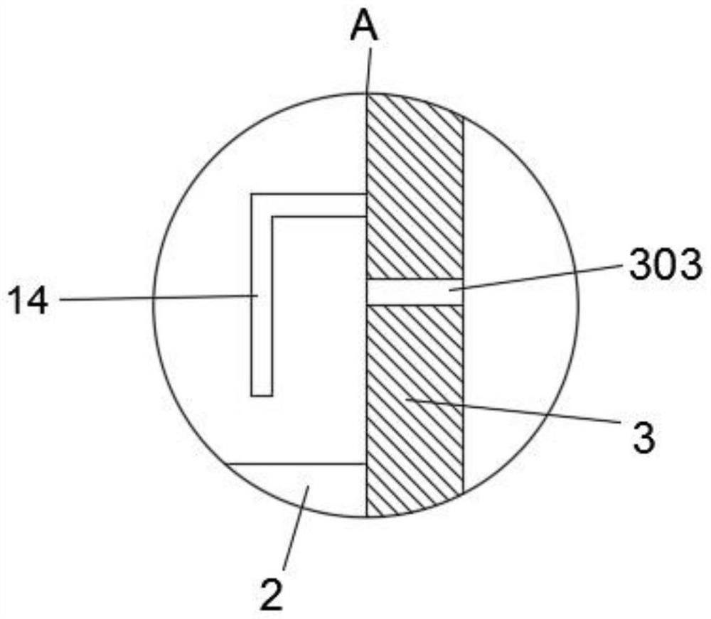
[0033] Box 1, the left side wall of the box 1 is fixed with a horizontal partition 2 and a longitudinal partition 3, and the horizontal partition 2 and the longitudinal partition 3 divide the box 1 into an atomization area and a liquid storage area , an atomizer 4 is installed in the atomization area, a water pump 5 is installed in the liquid storage area, a round hole 301 and a return groove 303 are arranged on the longitudinal partition 3, and the return flow groove 303 is located in the round hole The lower side of 301 is set in a flat shape, the side of the longitudinal partition 3 close to the transverse partition 2 is fixed with a baffle 14, the output end of the water pump 5 is connected to a water pipe 6, and the end of the water pipe 6 away from the water pump 5 runs through The round hole 301 extends into the atomization area;

[0034] The sealing...

Embodiment 2

[0038] On the basis of embodiment 1, the similarities with embodiment 1 will not be repeated, the difference is that, as Figure 2-6 As shown; the baffle 14 is L-shaped, including a connecting portion and a flow blocking portion, the connecting portion is located on the upper side of the backflow groove 303, the bottom end of the flow blocking portion extends to the lower side of the flow return groove 303, and the flow blocking portion There is a gap between the bottom end and the upper side of the transverse partition plate 2 .

[0039] The atomizer 4 is fixed on the upper side of the transverse partition 2 by screws, and the water pump 5 is fixed on the bottom wall of the box body 1 by screws.

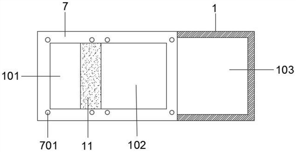
[0040] The top of the box body 1 is fixedly installed with a connecting plate 7, and the top of the box body 1 is sequentially provided with an air inlet 101, an air outlet 102, and an installation port 103 from left to right, and the deflector 11 is close to the air inlet 101 The ...

Embodiment 3

[0051] On the basis of the above embodiments, the difference is that, as figure 1 As shown; also includes a wire tube 12, used to dredge the various wires inside the box body 1, one end of the wire tube 12 extends to the outside of the box body 1 through the first wire hole 104, and the other end of the wire tube 12 passes through The second electric wire hole 302 extends to the inside of the atomizing area, and the electric wires of the fan 10 , the atomizer 4 and the water pump 5 all go through the electric pipe 12 and are connected to the external power supply.

[0052] Connect the wires of the fan 10, atomizer 4 and water pump 5 through the connection of the wire tube 12 to other PVC pipes, and lead out the box body 1 through the wire tube 12, which plays a good insulating role on the one hand and ensures the box body on the other hand. The neat internal wiring of the box body 1 effectively utilizes the internal space of the box body 1, and at the same time can ensure a go...


PUM


Abstract

The invention relates to the field of antibacterial protection equipment, and discloses a disinfection water tank for an AES antibacterial protection channel, the disinfection water tank comprises a tank body, a transverse partition plate and a longitudinal partition plate are fixedly mounted on the left side wall in the tank body, the transverse partition plate and the longitudinal partition plate divide the tank body into an atomization area and a liquid storage area, an atomizer is mounted in the atomization area, and the liquid storage area is connected with the atomizer. A water pump is installed in the liquid storage area, a round hole and a backflow groove are formed in the longitudinal partition plate, a baffle plate is fixedly installed on the side, close to the transverse partition plate, of the longitudinal partition plate, the output end of the water pump is connected with a water pipe, and the end, away from the water pump, of the water pipe penetrates through the round hole and extends into the atomization area. The sealing assembly comprises a connecting plate and a sealing plate and is used for sealing the atomization area; the mist outlet assembly comprises a mist outlet pipe, a fan and a flow guide plate and is used for discharging mist in the box body; the mist outlet efficiency is effectively improved, high-concentration mist is kept all the time, and therefore the better antibacterial protection effect can be achieved.

Description

Technical field: [0001] The invention relates to the field of antibacterial protection equipment, in particular to a disinfection water tank for an AES antibacterial protection channel. Background technique: [0002] The core technology of AES antibacterial protection channel is AES antibacterial and antiviral new material, which is a new epidemic prevention product specially designed to reduce the risk of epidemic transmission in public places. AES new material is a modified research and development on traditional photocatalytic materials. While enhancing the efficacy of photocatalytic particles, it can also be effectively and stably loaded on the surface of objects of different materials, without changing the principle of action of the particles, so that it has long-lasting antibacterial and antiviral effects. AES new material is also a subversive technology in the field of antibacterial and antiviral at home and abroad. The new AES material and water are mixed according...

Claims


Application Information

Patent Timeline
Patent Type & Authority Applications(China)
IPC IPC(8): A61L2/22A61L2/24A61L2/26
CPCA61L2/22A61L2/24A61L2/26A61L2202/14
Inventor 陈乃科
Owner 安徽同净枫翎新材料科技有限公司
Why Eureka
Try Eureka