Rolling type leveling mechanism

A roll-pressing and flat-rolling technology, applied in the field of lamination equipment, can solve the problems of many bubbles and low lamination efficiency, and achieve the effect of lamination flat

Inactive Publication Date: 2017-08-11
长兴昊太机械有限公司
View PDF1 Cites 10 Cited by
  • Summary
  • Abstract
  • Description
  • Claims
  • Application Information

AI Technical Summary

Problems solved by technology

[0004] The purpose of the present invention is to address the deficiencies of the prior art, by setting two smoothing rollers that can be spread out from the middle to both sides to s

Method used


Image

  • Rolling type leveling mechanism
  • Rolling type leveling mechanism
  • Rolling type leveling mechanism

Examples


Embodiment

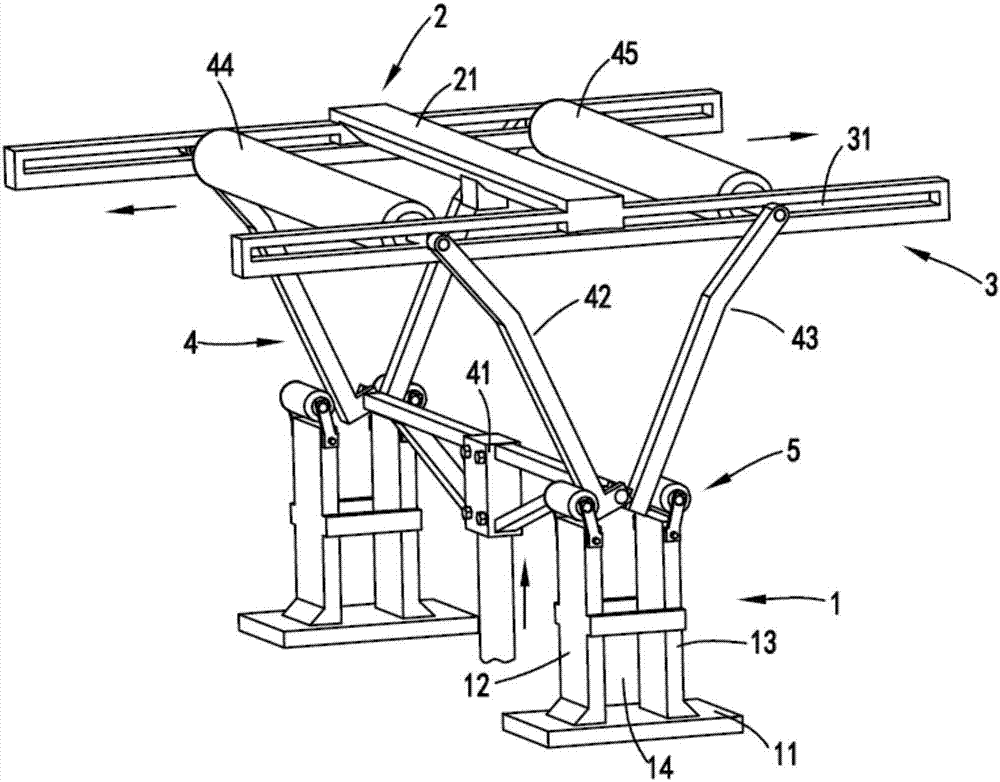
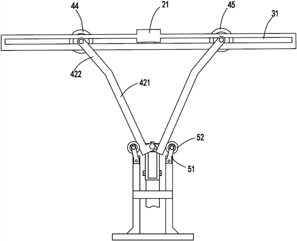
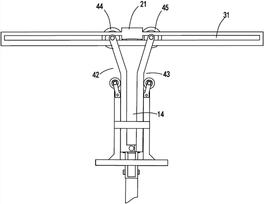
[0024] figure 1 It is a structural schematic diagram of a roller-type smoothing mechanism, figure 2 It is a schematic diagram of the smoothing roller a and smoothing roller b of the laminating device sliding to both sides, image 3 It is a schematic diagram of the front view of the initial state of the roller-type smoothing mechanism, Figure 4 Schematic diagram of the structure of the bonding device, Figure 5 It is a schematic diagram of the use state of the present invention. Such as figure 1 , figure 2 , image 3 , Figure 4 and Figure 5 As shown, a rolling type smoothing mechanism includes a limit device 1, a support device 2 for supporting the film, a guide device 3 arranged on both sides of the support device, and a guide device 3 for driving the support device 2 and a support device. The film on the device 2 moves upward along the limit device 1 to make the film contact with the workpiece to be filmed, and then moves to both sides along the guide device 3 so...


PUM


Abstract

The invention relates to a rolling smoothing mechanism, which includes a limit device, a support device for supporting a film, guide devices arranged on both sides of the support device, and a device for driving the guide device, the support device and the film along the support device. The limiting device moves upward to make the film contact with the workpiece to be filmed, and then moves along the guide device to both sides so that the film is completely attached to the surface of the workpiece; the invention overcomes the problems of low film sticking efficiency and many bubbles in the film sticking process.

Description

technical field [0001] The invention relates to the technical field of film sticking equipment, in particular to a rolling type smoothing mechanism. Background technique [0002] In order to prevent scratches or bruises during subsequent transportation, some sheets are often pasted with a layer of protective paper on their surface after processing. [0003] A Chinese invention patent with the authorized announcement number CN202037959U, which discloses a film and face paper device on the sheet metal uncoiling, leveling, and shearing production line, which accurately sends the sheet material, film tape or paper to the specified position through numerical control equipment Then use the film sticking roller to stick the film, but this equipment has the following problems: the equipment extends from one side to the other side during the film sticking process, and the film sticking efficiency is low and bubbles are prone to occur. Contents of the invention [0004] The purpose...

Claims


Application Information

Patent Timeline
IPC IPC(8): B65B33/02B65B61/24
CPCB65B33/02B65B61/24
Inventor 陈高春
Owner 长兴昊太机械有限公司
Why Eureka
Try Eureka