Pneumatic vehicle tire

A technology for pneumatic tires and vehicles, which is applied to vehicle parts, tire parts, tire treads/tread patterns, etc., can solve the problems of adverse effects of water-sliding characteristics, adverse effects of water-sliding functions, etc., and achieve simple service life, Improvement of water slide characteristics and mode optimization effect

Inactive Publication Date: 2017-08-29
CONTINENTAL REIFEN DEUTSCHLAND GMBH
View PDF7 Cites 0 Cited by
  • Summary
  • Abstract
  • Description
  • Claims
  • Application Information

AI Technical Summary

Problems solved by technology

As a result, the flow of water through the circumferential grooves and thus the hydroslide functionality is adversely affected
It is in the narrower circumferential grooves that the hydroplaning properties can therefore be adversely affected to a large extent and undesirably

Method used


Image

  • Pneumatic vehicle tire
  • Pneumatic vehicle tire
  • Pneumatic vehicle tire

Examples


Embodiment Construction

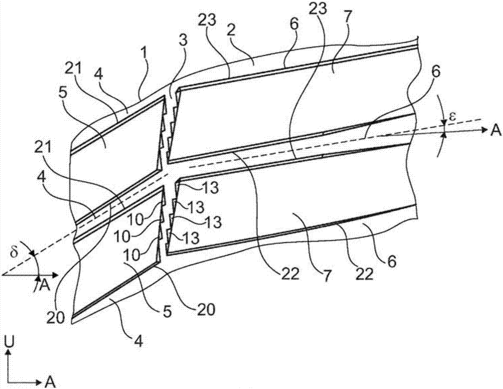
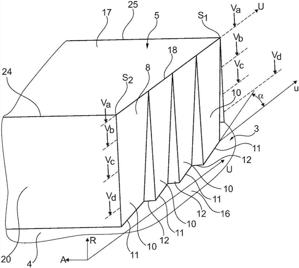
[0025] These figures show the tread pattern of a vehicle pneumatic tire for a known type of passenger motor vehicle (Pkw), where, as figure 1As shown, the block row 1 extending on the circumference of the vehicle pneumatic tire and the block row 2 extending on the circumference of the vehicle pneumatic tire are arranged side by side with each other in the axial direction A and passed through the vehicle pneumatic tire Circumferential grooves 3 extending circumferentially and oriented substantially in the circumferential direction U are separated from one another. The block row 1 is formed in a known manner from a plurality of block units 5 distributed over the circumference of the vehicle pneumatic tire, arranged one behind the other in the circumferential direction U of the vehicle pneumatic tire and Correspondingly, they are separated from each other by a plurality of oblique grooves 4 . The block row 2 is formed in a known manner from a plurality of block units 7 which are...


PUM


Abstract

The invention relates to a pneumatic vehicle tire, comprising a profiled tread having a circumferential groove (3), which separates radially raised profile elements (5, 7) arranged adjacent to each other from each other, wherein the circumferential groove (3) is bounded inwardly in the radial direction R by a groove base and axially by a groove wall on each of both sides of the groove base, wherein each of the profile elements (5, 7) separated by the circumferential groove (3) is bounded outwardly in the radial direction R of the tire by a radially outer surface and in the axial direction A toward the circumferential groove (3) by a flank (8, 9), which flanks extend in the radial direction R from the groove base (16) to the radially outer surface and each form one of the two groove walls, wherein extensions (10, 13) are formed toward the circumferential groove (3) on both flanks (8, 9), which extensions continuously broaden toward the groove base (16) and extend stepped in a saw-tooth shape in the circumferential direction U of the tire with alternatingly arranged first extension segments (11, 14) of the length L measured in the circumferential direction U, the greatest extension direction component of which is oriented in the circumferential direction U, and second extension segments (12, 15) of the length b measured in the circumferential direction U, the greater extension direction component of which is oriented in the axial direction A, wherein L > b, wherein the first extension segments (11, 14) of the saw-tooth-shaped course on the two flanks (8, 9) are oriented with the same inclination direction along the extent in the circumferential direction U, in such a way that an angle of inclination alpha is included together with the circumferential U in each case.

Description

technical field [0001] The invention relates to a pneumatic tire for vehicles having a profiled tread having a circumferential groove separating radially raised tread elements arranged side by side from one another, wherein the circumferential groove Bounded inwardly in radial direction R by a groove base and axially on both sides of the groove base by a groove wall respectively, wherein the sipe units separated by the circumferential grooves are in the Outwards in the radial direction R are bounded by a radially outer surface and in the axial direction A towards the circumferential groove by a side face which extends in the radial direction R from the groove base to the radially outer surface and respectively constitute one of the two sipe walls, wherein protrusions towards the circumferential sipe are formed at both sides, these protrusions widen continuously towards the sipe base and extend over the circumference of the tyre. Segmentally zigzag in direction U with alternat...

Claims


Application Information

Patent Timeline
IPC IPC(8): B60C11/11B60C11/13
CPCB60C11/11B60C11/1315B60C2011/0346B60C2011/0358B60C2011/1338
Inventor托尔斯滕·海因豪普特
OwnerCONTINENTAL REIFEN DEUTSCHLAND GMBH