Cooling device

A technology for cooling equipment and cooling chambers, applied to cooling machines, lighting and heating equipment, cooling fluid circulation devices, etc., can solve problems such as inconvenience, unobstructed access, and limited range of motion of cooling equipment, and achieve simple structural relationships , Reduce the structural prerequisite requirements, the effect of high service life

Inactive Publication Date: 2018-01-05
郭颂怡
View PDF7 Cites 0 Cited by
  • Summary
  • Abstract
  • Description
  • Claims
  • Application Information

AI Technical Summary

Problems solved by technology

In contrast to a door fixing with a tilting device, this door fixing can ensure a longer service life, because the parts of the opening device and the door are not subjected to relatively high loads when opening, but The disadvantage of this type of door mount is that when the door is opened, the door mount protrudes beyond the cooling device, which in turn limits the range of motion in the cooling device
This door fixture does not guarantee unobstructed access, which causes inconvenience

Method used


Image

  • Cooling device
  • Cooling device
  • Cooling device

Examples


Embodiment Construction

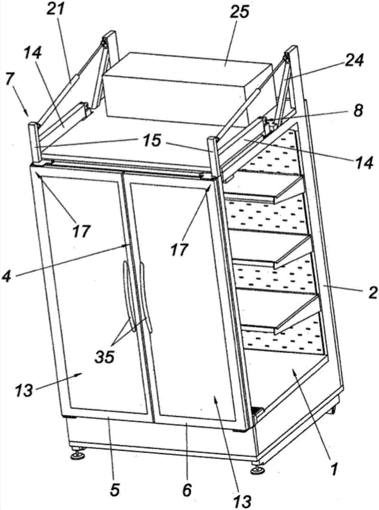
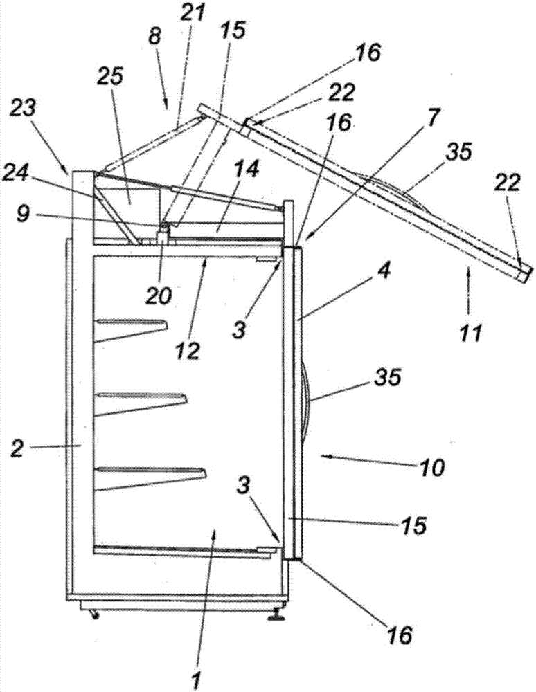
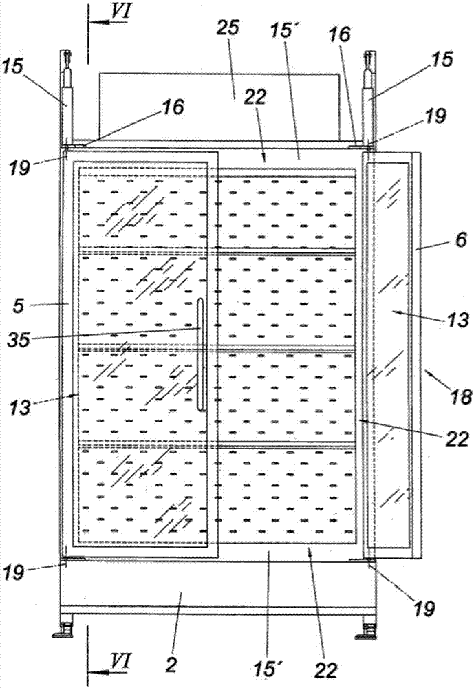
[0031] according to figure 1 The cooling device shown by way of example has a cooling chamber 1 for storing objects to be cooled (not shown in detail). The cooling chamber 1 is partially surrounded by a housing 2 . At the housing opening 3 of the housing 2 there is a door 4 with two door leaves 5 and 6 , wherein the door 4 is connected to the housing 2 via a door fastening 7 . The door fastening 7 enables the door to be moved in order to be able to access the contents of the cooling chamber 1 . This door movement takes place primarily by means of the opening device 8 . The opening device 8 enables the door 4 to be moved about the horizontal pivot axis 9 from the closed position 10 to the open position 11, wherein from figure 2 Two positions 10 and 11 can be seen. Although figure 2 The open position 11 shown in dotted lines is the end position, but other inverted open positions are also conceivable, but not shown for the sake of overview. The advantage of this open posi...


PUM


Abstract

The invention discloses a cooling device. The cooling device is provided with a cooling chamber (1), a shell (2), at least one door (4), and a door fixing piece (7), wherein the cooling chamber is used for storing a to-be-cooled article; the shell (2) at least partially accommodates the cooling chamber (1); the door (4) is arranged at a shell opening (3) of the shell (2), can move relative to theshell (2) and is used for allowing the article to enter the cooling chamber; the door fixing piece (7) is arranged between the door (4) and the shell (2). The door fixing piece (7) is provided with anopening device (8) provided with a turning rod (14). The door (4) can move from a closed position (10) to an open position (11) around a special horizontal turning axis (9) through the opening device(8). For achieving advantageous structural conditions, the door fixing piece (7) is provided with a support (15) which is connected with the turning rod (14) and particularly connected to the turningrod (14), the support (15) is used for bearing at least one component (16) of another opening device of the door fixing piece (7), and thus the door (4) can move from the closed position (10) to another open position (18), different from the open position (11), of another opening device (8).

Description

technical field [0001] The invention relates to a cooling device. Background technique [0002] In order to gain access to cooling chambers of cooling systems closed by doors, doors with various door fastenings are known, such doors enabling movement of the door from a closed position into an open position by means of an opening device. Thus, a door fastening is known, for example, from DE 140 1 078 A1, which fastens the door movably to the housing via a pivoting device. To this end, two turning levers are provided on the side of the door so that the door can be turned vertically upwards during its movement. Although such a door fastening enables unobstructed access to the cooling chamber of the cooling system, it has been shown that, in addition to the disadvantageously increased static prerequisites for the tilting mechanism, the tilting device is only suitable conditionally, which This is because the door thus pivoted reacts sensitively to the load forces caused by the ...

Claims


Application Information

Patent Timeline
Patent Type & Authority Applications(China)
IPC IPC(8): F25D11/00F25D17/06F25D23/02
Inventor 郭颂怡
Owner 郭颂怡
Why Eureka
Try Eureka