Energy-saving processing equipment used in early-stage production of non-woven cloth

A processing equipment and non-weft fabric technology, which is applied in the textile field, can solve the problems of cloth and film damage, low tearing efficiency, and unstable tearing process, so as to achieve improved effect, stable tearing process, and efficient tearing method. Effect

Active Publication Date: 2017-09-15
湖州蓝澳无纬布有限公司
View PDF5 Cites 4 Cited by
  • Summary
  • Abstract
  • Description
  • Claims
  • Application Information

AI Technical Summary

Problems solved by technology

[0003] The purpose of the present invention is to address the deficiencies of the prior art. By setting the heating part, the glue is first softened and then the separation film is torn off from the cloth by using the principle of negative pressure, thereby overcoming the tearing efficiency of the single-layer cloth for non-weft cloth. Low and unsteady during the film tearing process, it is easy to cause damage to the cloth and film

Method used


Image

  • Energy-saving processing equipment used in early-stage production of non-woven cloth
  • Energy-saving processing equipment used in early-stage production of non-woven cloth
  • Energy-saving processing equipment used in early-stage production of non-woven cloth

Examples


Embodiment 1

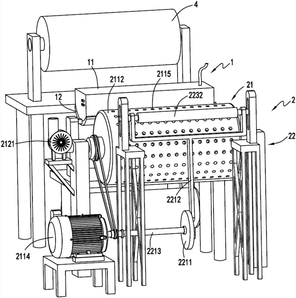
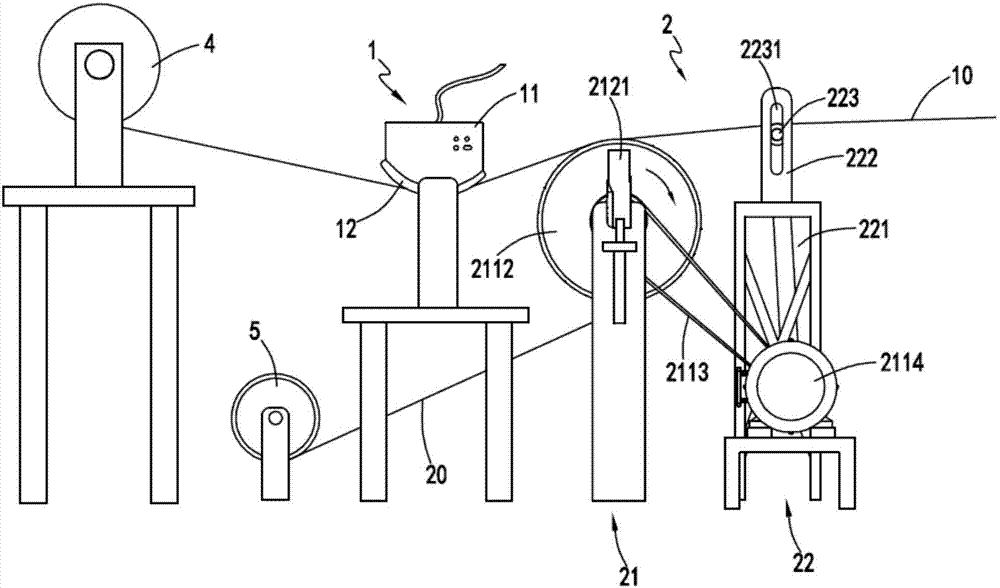
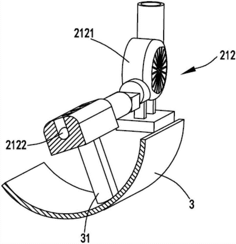
[0030] figure 1 It is a schematic diagram of the structure of the unidirectional fabric tearing film equipment for non-weft fabrics, figure 2 It is a schematic diagram of the front view of the unidirectional fabric tearing film equipment for non-weft fabrics, image 3 Schematic diagram of the suction device, Figure 4 It is a schematic diagram of the structure of the cloth pulling mechanism, Figure 5 is a schematic diagram of the structure of the roller, Figure 6 A cross-sectional schematic diagram of the roller. Such as figure 1 , figure 2 , image 3 , Figure 4 , Figure 5 and Figure 6 As shown, an energy-saving non-weft cloth production pre-processing equipment includes a heating part 1, and the heating part 1 is used to heat the cloth with film to soften the glue between the cloth 10 and the isolation film 20; the cloth film is separated Part 2, the cloth-film separation part 2 is arranged at the rear end of the heating part 1, the cloth-film separation part...

Embodiment 2

[0042] Such as figure 1 , figure 2 , image 3 , Figure 4 , Figure 5 and Figure 6 As shown, the components that are the same as or corresponding to those in the first embodiment are marked with the corresponding reference numerals in the first embodiment. For the sake of simplicity, only the differences from the first embodiment will be described below. The difference between the second embodiment and the first embodiment is that a baffle 3 is also provided inside the roller 2112, and the baffle 3 is fixed on the fixed shaft 2111 through a connecting piece 31, and the baffle 3 is used for Block the adsorption hole 2115 on the roller 2112 when it rotates to the baffle 3;

[0043] The setting of the baffle 3 makes the isolation film 20 move to the position of the baffle 3 with the roller 2112, because the baffle 3 blocks the adsorption hole 2115 on the roller 2112 in this area, so that when the isolation film 20 is transported to this area , the roller 2112 no longer has ...


PUM


Abstract

The invention relates to energy-saving processing equipment used in early-stage production of non-woven cloth. The energy-saving processing equipment comprises a heating part and a cloth and membrane separation part, wherein the heating part is used for heating membrane-carrying cloth to soften glue between the cloth and an isolating membrane; and the cloth and membrane separation part is arranged at the rear end of the heating part and used for separating the cloth from the isolating membrane of the cloth of which the glue is softened, and comprises a membrane adsorption mechanism for adsorbing the membrane and driving the isolating membrane to rotate together to change the transmission direction and a cloth pulling mechanism used for pulling the cloth in the direction opposite to the transmission direction of the isolating membrane. The problems that the single-cloth membrane stripping efficiency of the non-woven cloth is low and the cloth and the membrane have high probability of being damaged due to unstable membrane stripping are solved.

Description

technical field [0001] The invention relates to the technical field of textiles, in particular to an energy-saving pre-production processing equipment for weft-free fabrics. Background technique [0002] The strength of the unidirectional fabric is concentrated in a certain direction, and multiple unidirectional fabrics are cross-stacked at a certain angle to produce a weft-free fabric; in the production process of the unidirectional fabric, it is necessary to paste the produced unidirectional fabric with a film to prevent The one-way cloth is stained with dust and debris, and when it is made into a weft-free cloth, the film needs to be torn off from the one-way cloth. In the prior art, the film is generally torn by hand. It is easy to be torn, and the operator has a heavy workload, and may cause damage to the cloth. Contents of the invention [0003] The purpose of the present invention is to address the deficiencies of the prior art, by setting the heating part to softe...

Claims


Application Information

Patent Timeline
Patent Type & Authority Applications(China)
IPC IPC(8): B32B38/10
CPCB32B38/10
Inventor 许菱屠月新卢丹枫
Owner 湖州蓝澳无纬布有限公司
Why Eureka
Try Eureka