Novel IGBT current feedback dead time compensation method

A dead-time compensation and current feedback technology, applied in the field of dead-time compensation, can solve the problems of increased low-order harmonics, system instability, and reduced output voltage fundamental wave amplitude, achieving low-speed performance improvement, good compensation effect, and current The effect of waveform distortion rate reduction

Inactive Publication Date: 2017-09-15
NANJING UNIV OF SCI & TECH
View PDF3 Cites 3 Cited by
  • Summary
  • Abstract
  • Description
  • Claims
  • Application Information

AI Technical Summary

Problems solved by technology

[0003] The purpose of using the dead zone is to ensure the safety and reliability of the IGBT, but the setting of the dead zone also brings a dead zone effect to the inverter.
The main consequences will reduce the amplitude of the fundamental wave of the output voltage, increase the low-order harmonics, distort the current waveform, increase the harmonic loss of the motor, and even lead to system instability in severe cases

Method used


Image

  • Novel IGBT current feedback dead time compensation method
  • Novel IGBT current feedback dead time compensation method
  • Novel IGBT current feedback dead time compensation method

Examples


Embodiment

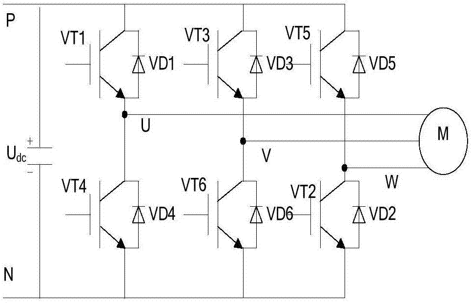
[0051] Usually in the inverter circuit of the frequency converter, the upper and lower power switching devices of the same phase bridge arm work in a complementary state. Such as figure 1As shown, the inverter circuit in the frequency converter is composed of 6 IGBT switch tubes, and the two switch tubes of VT1 and VT4, VT3 and VT6, VT5 and VT2 work in a complementary state respectively. The action of power devices requires a certain turn-on and turn-off time, and generally the turn-off time is longer than the turn-on time. In order to avoid shoot-through, time delay technology is adopted to insert enough dead time between the drive signals of the upper and lower transistors of the same-phase bridge arm to prevent shoot-through during the commutation process.

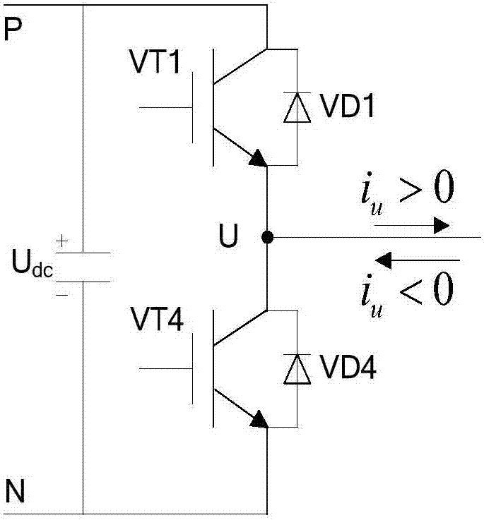
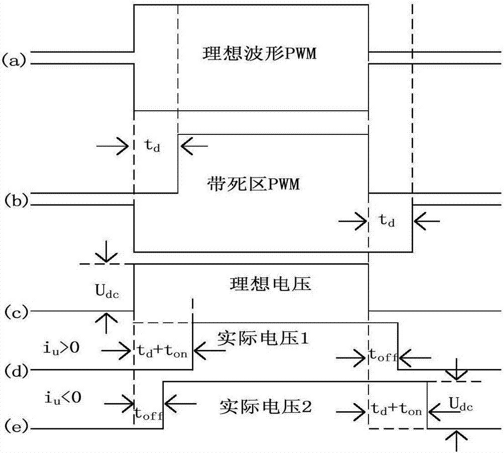
[0052] Take the U phase of the inverter as an example, assuming that i u A positive current flows out of the bridge arm, and a negative current flows into the bridge arm. Such as figure 2 As shown, when i u When >...


PUM


Abstract

The invention relates to an IGBT current feedback dead time compensation method comprising the following steps: designing a peripheral hardware circuit, sampling the output voltage of an inverter, and determining whether the voltage is at a high or low level; taking an output signal as an input signal of a current direction logic loop, and taking a drive signal of IGBTs in the upper and lower bridge arms of the inverter as a trigger signal through a logic OR gate; and inputting a final output signal of the hardware circuit to a microprocessor via an I / O port as a logic signal for judging the direction of current, getting the amount of dead time compensation through judgment, generating a PWM pulse needed, and finally completing dead time compensation. Through the method, the direction of current can be determined accurately. Moreover, whether the current is at a zero-crossing point can be determined, and transition compensation can be carried out in the zero-crossing point stage. The compensation effect is good. The current waveform distortion rate is decreased. The low-speed performance of motors is significantly improved.

Description

technical field [0001] The invention relates to a dead zone compensation method, in particular to a novel IGBT current feedback type dead zone compensation method. Background technique [0002] At present, more and more inverters use IGBTs as power switching devices. Since the power switching devices have a certain turn-on delay and turn-off delay, in order to prevent the upper and lower bridge arms of the inverter from passing through, causing a short circuit on the DC side, a microsecond-level dead time is added between the turn-on and turn-off of the IGBT . [0003] The purpose of using the dead zone is to ensure the safety and reliability of the IGBT, but the setting of the dead zone also brings a dead zone effect to the frequency converter. Its main consequences will reduce the amplitude of the fundamental wave of the output voltage, increase the low-order harmonics, distort the current waveform, increase the harmonic loss of the motor, and even lead to system instabi...

Claims


Application Information

Patent Timeline
Patent Type & Authority Applications(China)
IPC IPC(8): H02M1/38
CPCH02M1/38H02M1/385
Inventor 吕广强顾伟王佳佳梁凯歌陈曦
Owner NANJING UNIV OF SCI & TECH
Why Eureka
Try Eureka