Method for effectively inserting long spiral bored pile with post-inserted cage into vibration pipe

A technology of long helical drilling and vibrating tubes, which is applied to sheet pile walls, buildings, and infrastructure engineering, etc. It can solve the problems of slow pipe penetration and low efficiency, and achieve the effects of reducing pollution, safe and reliable construction, and saving construction time

Active Publication Date: 2017-10-10
北京中润宝成工程技术有限公司
View PDF5 Cites 1 Cited by
  • Summary
  • Abstract
  • Description
  • Claims
  • Application Information

AI Technical Summary

Problems solved by technology

[0004] The above pipe threading process requires a large site and a large crane

Method used


Image

  • Method for effectively inserting long spiral bored pile with post-inserted cage into vibration pipe
  • Method for effectively inserting long spiral bored pile with post-inserted cage into vibration pipe
  • Method for effectively inserting long spiral bored pile with post-inserted cage into vibration pipe

Examples


Embodiment 1

[0047] A method for efficiently inserting vibrating pipes into long auger drilled cast-in-place piles, comprising the following construction steps.

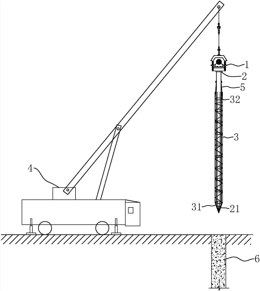
[0048] Step a, such as Figure 4 Shown, drill assembly hole 7 on the ground with the long helical drilling rig of construction concrete pile, and assembly hole 7 diameters are identical with the diameter of construction concrete pile, larger than reinforcement cage 3 diameters. refer to Image 6, 7 holes of assembling hole are darker than reinforcing cage 3 lengths 2~4m, can be 4m, can make reinforcing bar 32 of reinforcing bar 3 leak out assembling hole aperture 71, and make things convenient for the worker to hang lower hook 53 on reinforcing bar 32. Select the steel casing 8 whose diameter is larger than the reinforcement cage 3 and smaller than the assembly hole 7, and drive the steel casing 8 into the assembly hole 7 with the vibrating hammer 1 and the crane 4. The length of the steel casing 8 is greater than the depth of t...

Embodiment 2

[0053] like Figure 8 and Figure 9 As shown, the difference from Example 1 is that when the location of the assembly hole 7 is in good geology and the hole wall is not easy to collapse, the steel casing 8 is not set in the assembly hole 7, but the reinforcement cage 3 at the opening 71 of the assembly hole It needs to be fixed with a temporary fixing device 9, and the specific method is as follows:

[0054] Step b, after the reinforcement cage 3 is vertically lowered into the assembly hole 7, three positioning piles 91 are vertically driven into the ground 2 meters outside the opening of the assembly hole 71, and the three positioning piles 91 form an equilateral triangle. A pull-joint rope 92 with fixed hook 93 is bolted on one end, hooks the reinforcing rib 32 on the reinforcement cage 3 with the fix hook 93, and three pull-join ropes 92 have the same length, and when they are all in a tight state, the center of the reinforcement cage 3 That is, it is located in the cente...


PUM

PropertyMeasurementUnit
Lengthaaaaaaaaaa

Abstract

The invention discloses a method for effectively inserting a long spiral bored pile with a post-inserted cage into a vibration pipe. According to the key points of the technical scheme, the method comprises the following construction steps that a, an assembly hole with the diameter larger than the diameter of a steel reinforcement cage is drilled in the ground; b, the steel reinforcement cage is vertically hoisted into the assembly hole; c, the vibration pipe is hoisted into the steel reinforcement cage in the assembly hole, wherein the bottom of the vibration pipe is made to abut against the conical portion of the steel reinforcement cage; and d, a vibration hammer, the vibration pipe and the steel reinforcement cage are hoisted to the upper portion of a concrete pile to be subjected to cage insertion, and insertion of the steel reinforcement cage into the concrete pile begins. By means of the method, pipe penetration operation which is originally carried out on the ground is changed to be carried out in the special assembly hole, the pipe penetration operation is changed to be in the vertical direction from the horizontal direction, original manual pipe penetration is changed to mechanical pipe penetration, the high requirements on construction sites and the arm length of a crane are lowered, and the construction efficiency is greatly improved.

Description

technical field [0001] The invention relates to the technical field of construction of long auger bored cast-in-place piles, in particular to a method for inserting a long auger-drilled cast-in-situ pile into a vibrating tube. Background technique [0002] The cast-in-place pile with long auger drilling is a kind of reinforced concrete pile foundation. Its main process is that after the long auger drilling machine completes the drilling, the concrete is poured first, and then the steel cage is vibrated and inserted into the concrete pile with a vibrating hammer. Compared with the process of "hanging the reinforcement cage first and then pouring concrete", this construction technology has the advantages of fast hole formation and pile formation, easy guarantee of pile quality, and high single pile bearing capacity, so it is now widely used and promoted. [0003] like image 3 As shown, before the reinforcement cage 3 is inserted into the concrete for the post-insertion cast-i...

Claims


Application Information

Patent Timeline
IPC IPC(8): E02D5/34
CPCE02D5/34
Inventor 郝丙军陈世成
Owner 北京中润宝成工程技术有限公司
Why Eureka
Try Eureka