Optical module and network equipment

A technology of network equipment and optical modules, applied in the field of optical communication, can solve the problem of high bandwidth occupancy rate

Active Publication Date: 2017-11-10
HUAWEI TECH CO LTD
View PDF13 Cites 5 Cited by
  • Summary
  • Abstract
  • Description
  • Claims
  • Application Information

AI Technical Summary

Problems solved by technology

[0004] This application provides an optical module and network equipment, which are u

Method used


Image

  • Optical module and network equipment
  • Optical module and network equipment
  • Optical module and network equipment

Examples


Embodiment Construction

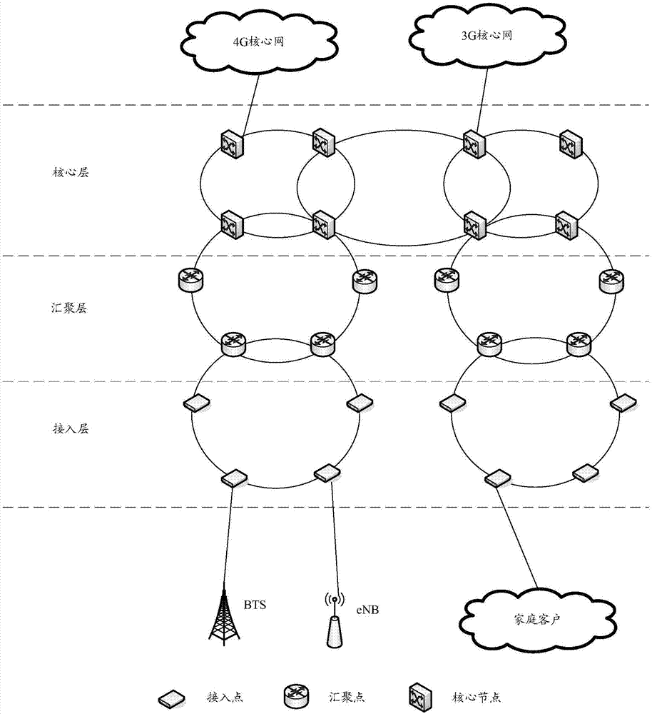
[0046] see figure 1 As shown in FIG. 1 , it is an architectural diagram of the metropolitan area network based on the embodiment of the present application. The metropolitan area network mainly includes three layers, which are the access layer, aggregation layer and core layer. The core layer mainly provides high-bandwidth service bearing and transmission, and completes the interconnection with the existing network. The existing network can include asynchronous transfer mode (English: asynchronous transfer mode, referred to as: ATM) network, digital data network (English: digital data network, referred to as: DDN), Internet Protocol (English: internet protocol, referred to as: IP) network, etc. The main function of the aggregation layer is to provide service access nodes with the aggregation and distribution of user service data, and at the same time realize the service level classification of services. The access layer utilizes multiple access technologies to allocate bandw...


PUM


Abstract

The invention discloses an optical module and network equipment and aims to solve a problem of a relatively high processing bandwidth occupancy rate of an optical module in the prior art. The optical module is arranged at first network equipment of an access ring, the access ring comprises second network equipment and third network equipment, the second network equipment and the third network equipment are in optical connection with the first network equipment, the first network equipment is applied to an access point, the optical module comprises a first multi/demultiplexer and an optical receiver, wherein the first multi/demultiplexer is used for receiving first optical signals from the second network equipment, separating second optical signals having first wavelengths from the first optical signals and transmitting the second optical signals to the light receiver, the first multi/demultiplexer is further used for transmitting third optical signals to the third network equipment, the third optical signals are other optical signals which are separated from the first optical signals and have other wavelengths except the first wavelengths, and the light receiver is used for receiving the second optical signals.

Description

technical field [0001] The present application relates to the technical field of optical communication, and in particular to an optical module and network equipment. Background technique [0002] With the development of communication technology, in the 5th generation (English: the 5th generation, 5G for short) communication technology, the bandwidth requirements of the bearer network are getting higher and higher. [0003] In the current metropolitan area bearer network, the network is formed based on the packet transport network (English: packet transport network, PTN for short), and the access layer adopts the access ring. The access ring includes multiple PTN devices. Multiple PTN devices include PTN devices as access points and PTN devices as convergence points. Each PTN device includes an optical module. The bandwidth supported by the optical module included in each PTN device on the existing general access ring is also It represents the bandwidth supported by the PTN ...

Claims


Application Information

Patent Timeline
IPC IPC(8): H04B10/27H04B10/69H04L12/28G02B6/42G02B6/43
CPCG02B6/4293G02B6/43H04B10/27H04B10/69H04L12/2885H04J14/0206H04J14/0216H04J14/0283H04J14/0205H04Q11/0067H04Q2011/0092
Inventor 陈国导李春荣
Owner HUAWEI TECH CO LTD
Why Eureka
Try Eureka