Radar echo delay coherent simulation method based on digital radio frequency memory

A digital radio frequency storage, radar echo technology, applied in radio wave measurement systems, instruments, etc., can solve the problems of limited frequency discrimination range, difficult phase-locked loop phase-locked tracking, difficult simulator regeneration frequency reference, etc., to achieve flexible improvement. performance, improved accuracy, wide adaptability

Active Publication Date: 2017-11-14
BEIJING INSTITUTE OF TECHNOLOGYGY
View PDF3 Cites 3 Cited by
  • Summary
  • Abstract
  • Description
  • Claims
  • Application Information

AI Technical Summary

Problems solved by technology

This method eliminates the false delay, but the general frequency discrimination range of the phase-locked loop is limited. For the large-bandwidth signal generated by the radar, it is difficult for the phase-locked loop to phase-lock and track, and it is difficult to accurately generate a simulator regeneration frequency reference that is coherent with the radar reference frequency, resulting in It is Difficult to Realize Coherent Simulation of Radar Echo Delay Using Phase-locked Regeneration

Method used


Image

  • Radar echo delay coherent simulation method based on digital radio frequency memory
  • Radar echo delay coherent simulation method based on digital radio frequency memory
  • Radar echo delay coherent simulation method based on digital radio frequency memory

Examples


Embodiment 1

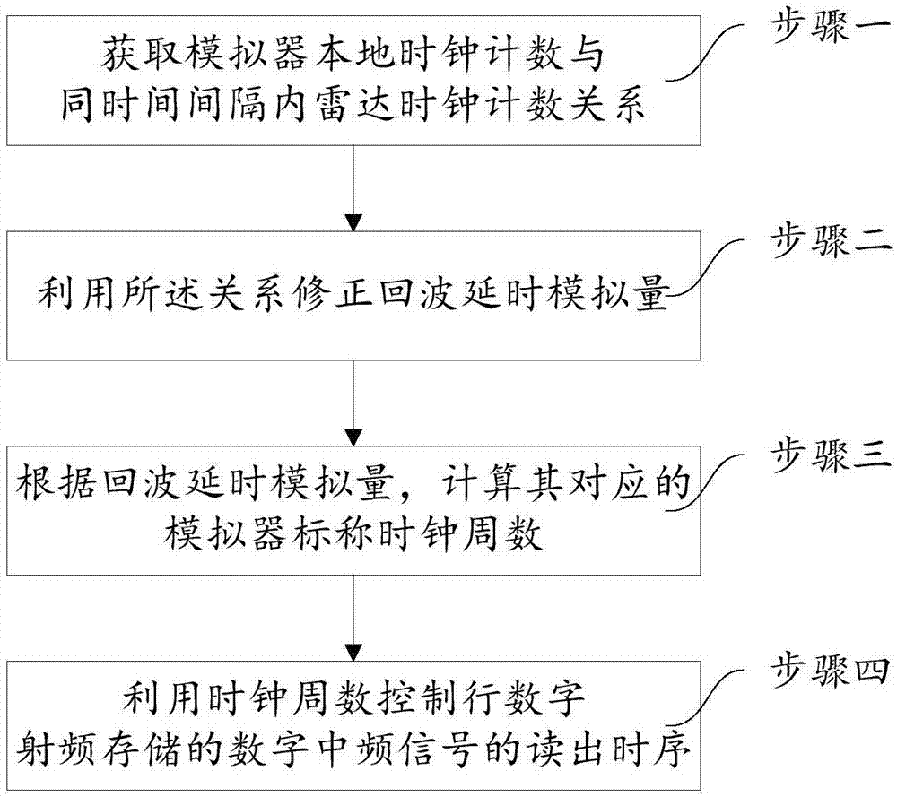
[0024] This example is based on the radar echo delay coherent simulation method of digital radio frequency storage. In this example, the radar transmit signal is a linear frequency modulation signal, and the specific process is as follows:

[0025] Step 1: The simulator receives the signal model

[0026] The simulator receives the pulse-modulated chirp signal emitted by the radar, which is expressed as follows:

[0027]

[0028] In the formula, f 0 is the radar transmit carrier frequency, T p is the pulse width, T r is the pulse repetition period, A is the amplitude of the chirp signal, and K is the chirp modulation coefficient B is the chirp bandwidth, is the initial phase of the radar transmitting carrier, Rect(t) is a rectangular pulse function, defined as follows:

[0029]

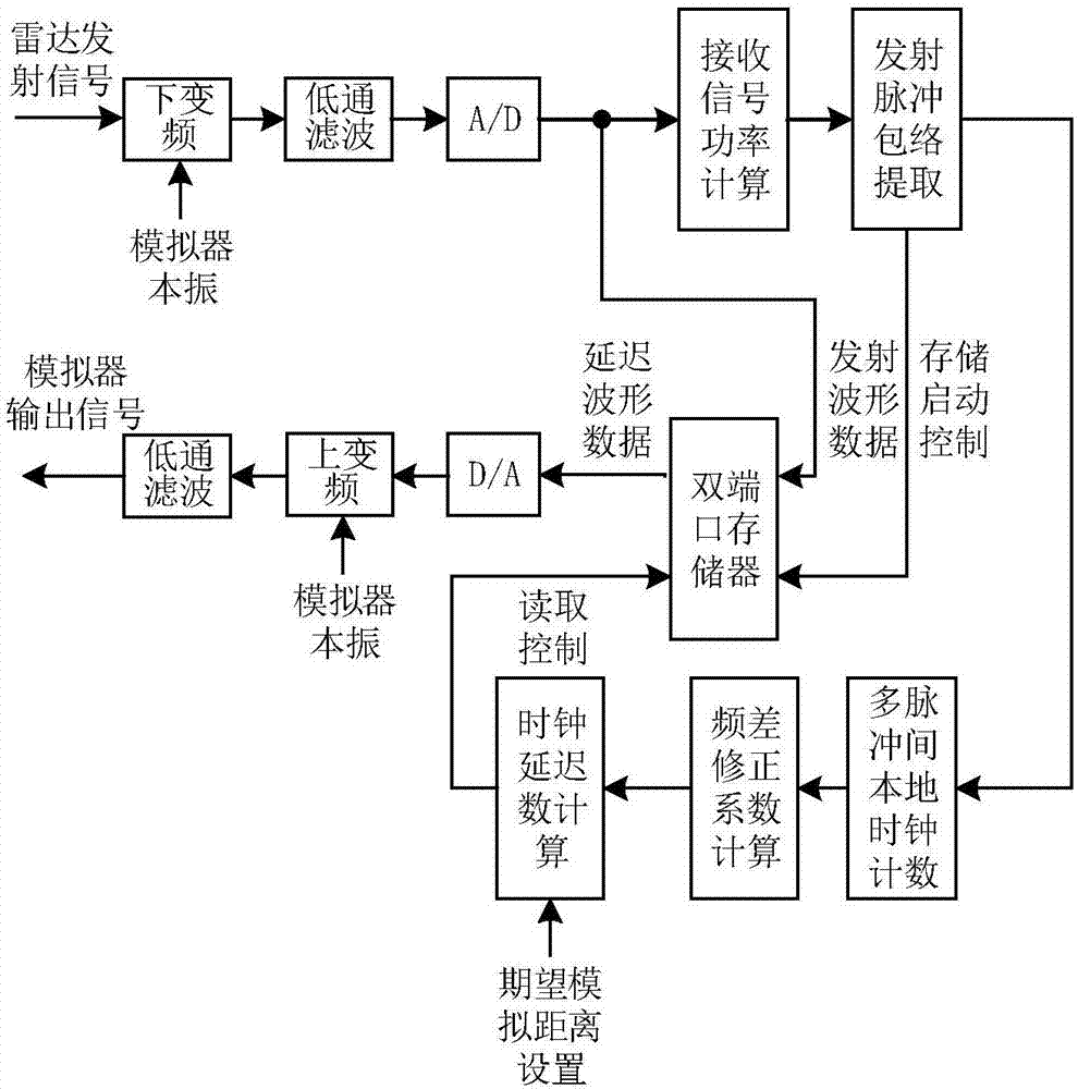
[0030] Step 2: Distance Delay Coherent Simulation

[0031] The simulator uses frequency f Lo_sim After down-conversion, low-pass filtering, and A / D converter sampling of the received sig...

Embodiment 2

[0071] This example is based on the radar echo delay coherent simulation method of digital radio frequency storage. In this example, the radar transmit signal is a linear frequency modulation signal, and the nominal frequency of the radar and the simulator is 300MHz, that is, f' clk_radar =f' clk_sim =300MHz, The quasi-stability of the radar clock is 10ppm, that is, the actual frequency f of the radar operating clock clk_radar =300×(1+10 -5 )MHz; the quasi-stability of the simulator clock is -10ppm, that is, the actual frequency f of the simulator working clock clk_sim =300×(1-10 -5 ) MHz. Consider the radar operating clock count N 1 = 750000 clock cycles, generating cycle The specific process of this method is:

[0072] Step 1: The simulator receives the signal model

[0073] The simulator receives the chirp transmit signal, which is expressed as follows:

[0074]

[0075] In the formula, T P =0.5×(1-10 -5 )ms is the width of the radar transmit pulse, f 0 =15...


PUM


Abstract

The invention provides a radar echo delay coherent simulation method based on a digital radio frequency memory, which includes the following steps: S1, a simulator extracts the envelope of radar transmitted signal pulses, and uses a local clock to perform clock counting N3 in N2 radar transmitted pulse cycles; S2, the echo delay analog quantity tau'(n) after correction is calculated; S3, the nominal clock cycle number k' of the corresponding simulator is calculated according to the echo delay analog quantity tau'(n); and S4, the readout sequence of digital medium-frequency signals obtained after processing by the simulator and saved in a digital radio-frequency form is controlled using the k' value, thus completing radar echo delay simulation. Through the method, coherent simulation of radar echo delay can be completed quickly.

Description

technical field [0001] The invention relates to a radar echo delay coherent simulation method, in particular to a radar echo delay coherent simulation method based on digital radio frequency storage, and belongs to the technical field of radar echo simulation. Background technique [0002] Radar echo simulation is the product of the combination of system simulation technology and radar technology. The object simulated by radar echo simulation technology is the target and environment of the radar, and the result of the simulation is to reproduce the radar echo signal containing the information of the radar target and the target environment. The core of pulse radar echo simulation is to simulate the delay that directly reflects the relative distance information between the radar and the target. However, when the radar echo simulator (hereinafter referred to as the simulator) is different from the radar reference clock, there will be a spurious delay in the radar echo delay sim...

Claims


Application Information

Patent Timeline
Patent Type & Authority Applications(China)
IPC IPC(8): G01S7/40
CPCG01S7/4052
Inventor 崔嵬侯建刚刘芳政沈清向锦志吴嗣亮
Owner BEIJING INSTITUTE OF TECHNOLOGYGY
Why Eureka
Try Eureka