
Valve assembly
A valve component and valve module technology, applied in the direction of servo motor components, valve details, valve devices, etc., can solve the problem that the status information of a single valve module cannot be assigned to this valve module, and achieve the effect of easy reading
- Summary
- Abstract
- Description
- Claims
- Application Information
AI Technical Summary
Problems solved by technology
Method used
Image

Examples
Embodiment Construction
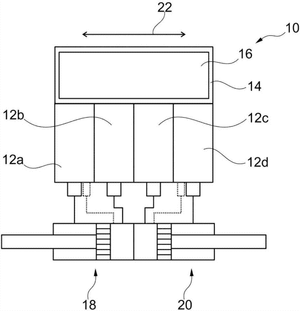
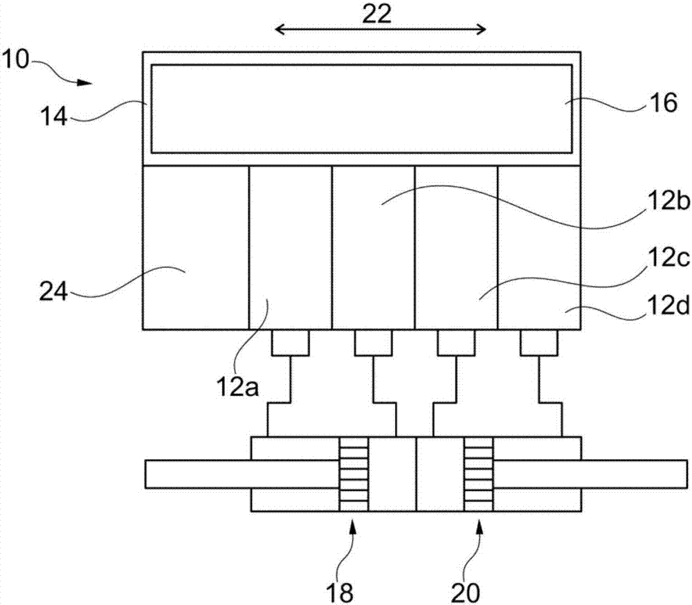
[0033] figure 1 A first embodiment of a valve assembly 10 comprising four valve modules 12a to 12d is shown.
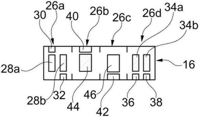
[0034] Also arranged in the valve assembly 10 is a display module 14 in which a display device 16 in the form of a display is arranged.
[0035] A first part 18 in the form of an actuator (here a first pneumatic cylinder or a first pneumatic valve) is connected to the valve modules 12a and 12b, and a second part 20 in the form of a second actuator (here a pneumatic cylinder or a second pneumatic valve) are connected to the valve modules 12c and 12d so that each valve module has an integrated solenoid valve.
[0036] Typically, however, the valve module has two solenoid valves and thus two outputs to which eg pneumatic cylinders or pneumatic valves on opposite sides of the piston or actuating member are connected, i.e. one solenoid valve for ventilation and a solenoid valve for exhaust. The pneumatic valve is then closed by a spring and opened by air.
[0037] exis...
PUM
 Abstract
Description
Claims
Application Information