Device and method for measuring geometric parameters of elongated holes

A technology of geometric parameters and measuring devices, applied in measuring devices, optical devices, instruments, etc., to reduce the source of errors, easy to operate, and small size of the probe

Active Publication Date: 2020-01-14
XIAN UNIV OF TECH
View PDF14 Cites 0 Cited by
  • Summary
  • Abstract
  • Description
  • Claims
  • Application Information

AI Technical Summary

Problems solved by technology

[0005] The purpose of the present invention is to provide a device and method for measuring the geometric parameters of elongated holes, so as to solve the technical problems existing in the prior art

Method used


Image

  • Device and method for measuring geometric parameters of elongated holes
  • Device and method for measuring geometric parameters of elongated holes
  • Device and method for measuring geometric parameters of elongated holes

Examples


Embodiment 1

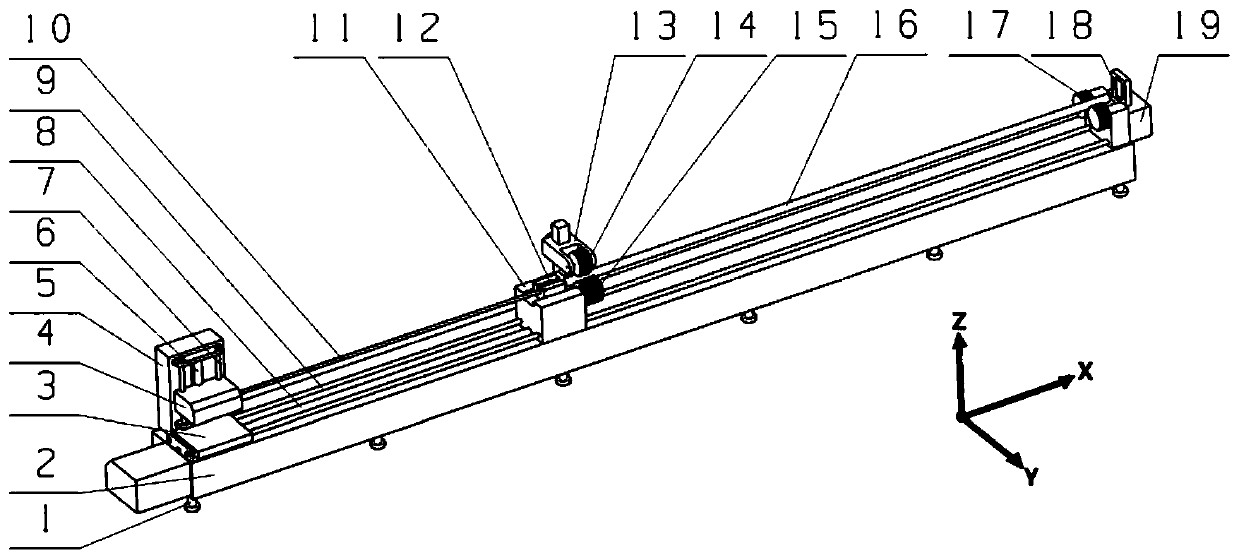
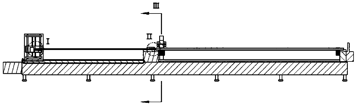
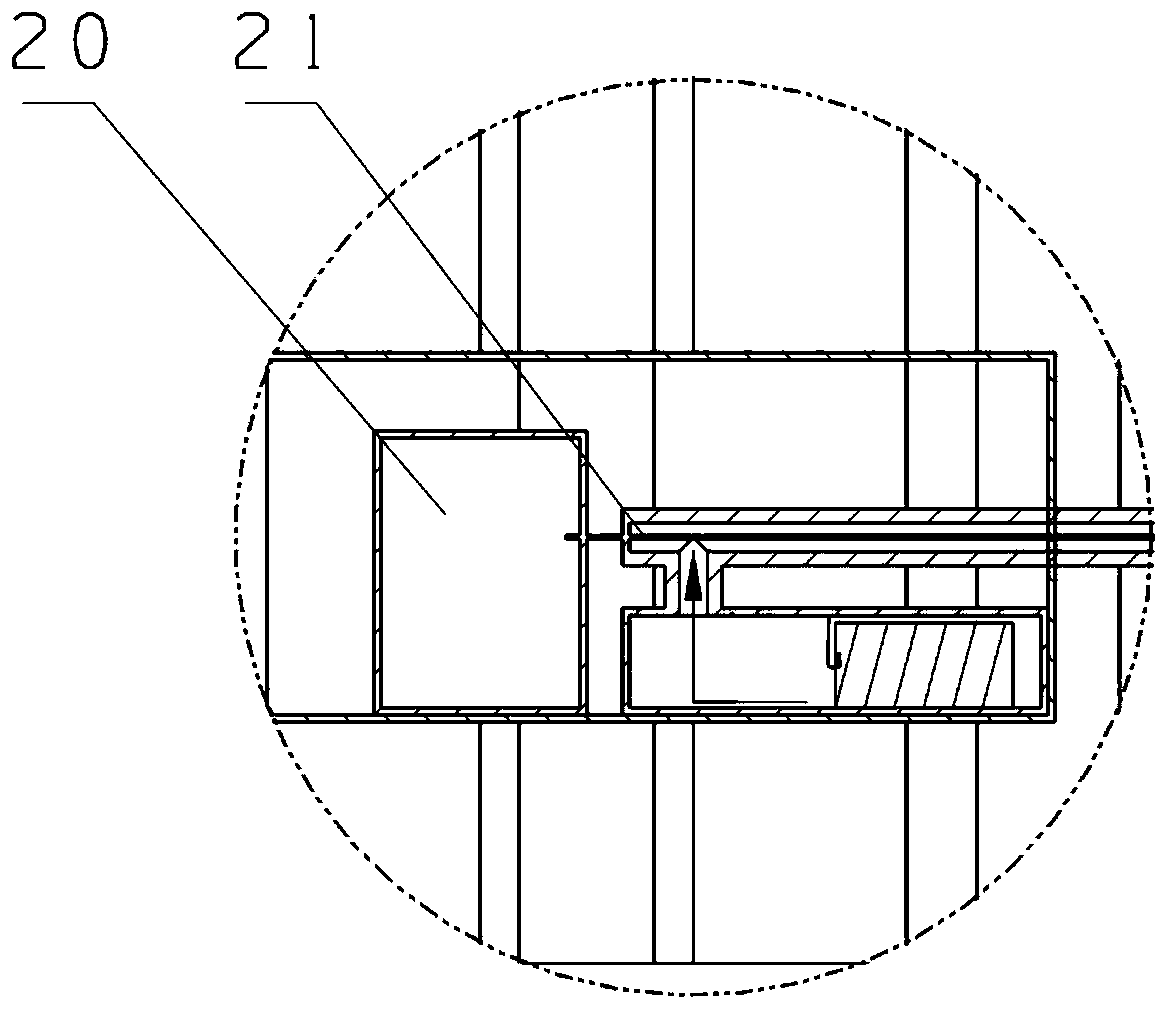
[0044] to combine Figure 1 to Figure 5 As shown, the present embodiment provides a device for measuring the geometric parameters of elongated holes, which includes: a positioning mechanism, a traveling mechanism and a measuring mechanism; the positioning mechanism is used to automatically center the position of the workpiece 16 to be measured; the measuring The mechanism includes: self-centering measuring head 12, toughness measuring rod 10, laser 20, pneumatic sensor and CCD processor 18; said toughness measuring rod 10 is provided with an internal passage along its axial direction, and The first end is provided with an air inlet, and the second end of the toughness measuring rod 10 is provided with an automatic centering probe 12, and the automatic centering probe 12 includes: a pneumatic centering probe and a laser sight 22; The laser 20 is arranged on the walking mechanism, and the optical fiber 21 of the laser 20 is passed through the inner channel of the toughness measu...

Embodiment 2

[0060] to combine Figure 1 to Figure 5 As shown, this embodiment also provides a method for measuring the device for measuring the geometric parameters of elongated holes according to Embodiment 1, which includes the following steps:

[0061] One), realizing the automatic centering of the workpiece 16 to be measured by the positioning mechanism; as a further technical solution, the automatic centering of the workpiece 16 to be measured by the positioning mechanism includes the following steps: wherein, the positioning mechanism includes: Workbench 2, positioning seat 11 and sliding seat 19; The first end of described traveling mechanism is arranged on described workbench 2, described slide seat 19 is arranged on the second end of described workbench 2, described Positioning seat 11 is arranged on the middle section of described workbench 2, is provided with elastic pressing mechanism 13 on described positioning seat 11, and described elastic pressing mechanism 13 is provided ...


PUM


Abstract

The invention relates to the technical field of photoelectric detection, and especially relates to a device and method for measuring the geometric parameters of a long and thin hole. The device comprises a positioning mechanism, a traveling mechanism and a measurement mechanism. The positioning mechanism is used for the automatic centering of a to-be-detected workpiece. The measurement mechanism comprises an automatic centering head, a toughness measuring rod, a laser, a pneumatic sensor, and a CCD processor. An optical fiber of the laser passes through an internal channel of the toughness measuring rod to be connected with a laser sight, and the laser sight is in signal connection with the CCD processor. An air source of the pneumatic sensor is communicated with a pneumatic centering measuring head through an air inlet of the toughness measuring rod. The traveling mechanism is used for carrying the toughness measuring rod to move, and enabling an automatic centering measuring head atthe second end to move to the inlet of the long and thin hole of the to-be-detected workpiece. The device can achieve the detection of the linearity of the axis and roundness of the long and thin holeconveniently, and is not limited by the rigidity and length of the measuring rod.

Description

technical field [0001] The present invention relates to the technical field of photoelectric detection, in particular to a device and method for measuring geometric parameters of elongated holes, and in particular to a device and method for measuring the straightness and roundness of the axes of elongated holes. Background technique [0002] The straightness and roundness detection of the slender hole axis is an important part in the processing of slender hole parts, an important means of quality control and management of slender hole parts, and a technical guarantee for implementing quality standards. The measurement of the straightness and roundness of the axis of the slender hole is of great significance to the rational use of industrial production and products, especially for the aerospace and weapon industries, the straightness of the axis and the roundness of the inner hole are very important indicators, which directly affect Performance and weapon accuracy of slender ...

Claims


Application Information

Patent Timeline
Patent Type & Authority Patents(China)
IPC IPC(8): G01B11/27G01B11/24
CPCG01B11/2408G01B11/272
Inventor 邵伟彭鹏高瑞鹏王晓娟王错
Owner XIAN UNIV OF TECH
Why Eureka
Try Eureka