Electric cooker and heating control system and control method thereof

A heating control and cooker technology, applied in the direction of preventing overflow, can solve the problems of complex assembly process, overflow of steam foam, increase manufacturing cost, etc., and achieve the effects of reducing manufacturing cost, preventing foam overflow, and simplifying assembly process

Active Publication Date: 2018-04-06
FOSHAN SHUNDE MIDEA ELECTRICAL HEATING APPLIANCES MFG CO LTD
View PDF6 Cites 8 Cited by
  • Summary
  • Abstract
  • Description
  • Claims
  • Application Information

AI Technical Summary

Problems solved by technology

However, if the electric cooker is filled with a little more water, the heating power is too high, or it is in a plateau area, when a large amount of steam foam is generated, it is difficult for the steam valve to turn all the steam foam into liquid backflow, which will cause a large amount of steam foam to overflow and affect the taste of rice , and will stain the counter top, making it difficult to clean
[0003] The related technology proposes a way to detect overflow by adding electrodes on the cover of the electric cooker. However, the disadvantage of the related technology is that the electrodes are directly connected to the circuit as a conductor, so in order to avoid electric shock to the human body, an isolated power supply is used. Separated from the strong electricity, it increases the manufacturing cost, and the assembly process is also more complicated
In addition, in related technologies, low-power heating is used to prevent steam bubbles from overflowing, resulting in insufficient boiling during the heating process and poor rice taste

Method used


Image

  • Electric cooker and heating control system and control method thereof
  • Electric cooker and heating control system and control method thereof
  • Electric cooker and heating control system and control method thereof

Examples


Embodiment Construction

[0041] Embodiments of the present invention are described in detail below, examples of which are shown in the drawings, wherein the same or similar reference numerals designate the same or similar elements or elements having the same or similar functions throughout. The embodiments described below by referring to the figures are exemplary and are intended to explain the present invention and should not be construed as limiting the present invention.

[0042] The electric cooker and its heating control system and control method proposed by the embodiments of the present invention are described below with reference to the accompanying drawings.

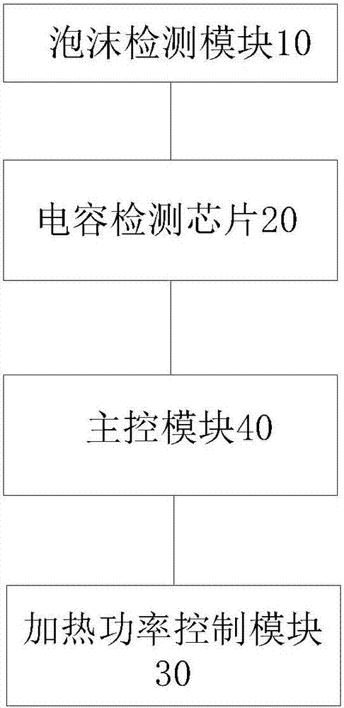
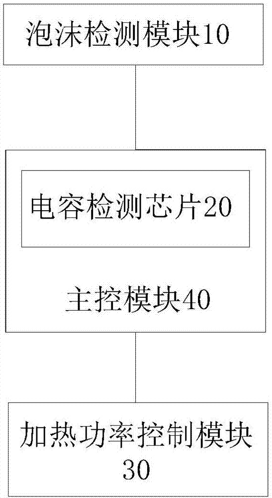
[0043] figure 1 is a schematic block diagram of a heating control system for an electric cooker according to an embodiment of the present invention. Such as figure 1 As shown, the heating control system includes: a foam detection module 10 , a capacitance detection chip 20 , a heating power control module 30 and a main control module ...


PUM


Abstract

The invention discloses an electric cooker and a heating control system and control method thereof. The system comprises a foam detection module, a capacitance detection chip, a heating power controlmodule and a main control chip; the foam detection module is arranged in an upper cover of the electric cooker and comprises at least one foam sensing component, wherein the capacitance value of the foam detection module changes when each foam sensing component senses steam foam generated by the electric cooker; the capacitance detection chip is connected with the foam detection module and generates a foam detection signal by detecting the change condition of the capacitance value of the foam detection module; the heating power control module is used for controlling the heating power of the electric cooker; the main control module is connected with the capacitance detection chip and the heating power control module separately and used for controlling the electric cooker to stop heating orreduce the power for heating through the heating power control module when the capacitance value change of the foam detection module is determined according to the foam detection signal, so that an overflow phenomenon is prevented from occurring on the electric cooker, full boiling is ensured, and the non-electric contact detection of the foam is achieved.

Description

technical field [0001] The invention relates to the technical field of electric appliances, in particular to a heating control system of an electric cooker, an electric cooker and a heating control method of the electric cooker. Background technique [0002] Related electric cookers are usually provided with a steam valve on the upper cover to break the foam through the steam valve, so that the steam foam becomes liquid backflow. However, if the electric cooker adds a little more water, the heating power is too high, or it is in a plateau area, when a large amount of steam foam is generated, it is difficult for the steam valve to turn all the steam foam into liquid backflow, which will cause a large amount of steam foam to overflow and affect the taste of rice. , and will stain the counter top, making it difficult to clean. [0003] The related technology proposes a way to detect overflow by adding electrodes on the cover of the electric cooker. However, the disadvantage of...

Claims


Application Information

Patent Timeline
Patent Type & Authority Applications(China)
IPC IPC(8): A47J27/62
CPCA47J27/62
Inventor 刘文华王云峰雷俊黄庶锋彭晶艾永东
Owner FOSHAN SHUNDE MIDEA ELECTRICAL HEATING APPLIANCES MFG CO LTD
Why Eureka
Try Eureka