Fatigue break feeding machine for fixed workpiece fatigue load circumferential cyclic loading

A technology of fatigue loading and cyclic loading, which is applied in the direction of manufacturing tools, metal processing equipment, feeding devices, etc., can solve problems such as poor section quality, low production efficiency, and high energy consumption, and achieve good section quality, simple structure, and high efficiency. high effect

Active Publication Date: 2018-05-18
XIAN UNIV OF TECH
View PDF9 Cites 8 Cited by
  • Summary
  • Abstract
  • Description
  • Claims
  • Application Information

AI Technical Summary

Problems solved by technology

However, the traditional shearing, sawing and laser cutting and other emerging cutting and blanking methods have problems such as low material utilization rate, large blanking force, low production efficiency, high energy consumption, and poor section quality to varying degrees, which do not meet the requirements of green technology. Manufacturing and Precision Manufacturing Requirements
[0003] The traditional blanking methods include lathe cutting and sawing. Although these two blanking methods can obtain a flat section, they have disadvantages such as low production efficiency and waste of raw materials.
For this re

Method used


Image

  • Fatigue break feeding machine for fixed workpiece fatigue load circumferential cyclic loading
  • Fatigue break feeding machine for fixed workpiece fatigue load circumferential cyclic loading
  • Fatigue break feeding machine for fixed workpiece fatigue load circumferential cyclic loading

Examples


Embodiment Construction

[0022] The present invention will be described in detail below in conjunction with the accompanying drawings and specific embodiments.

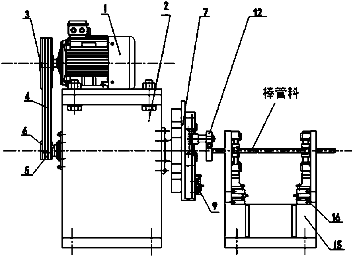
[0023] see figure 1 The present invention provides a fatigue fracture blanking machine that does not move the workpiece fatigue load and is loaded circularly in the circumferential direction. It consists of three parts: a loading frequency control mechanism, a fatigue load loading mechanism and a workpiece clamping mechanism.

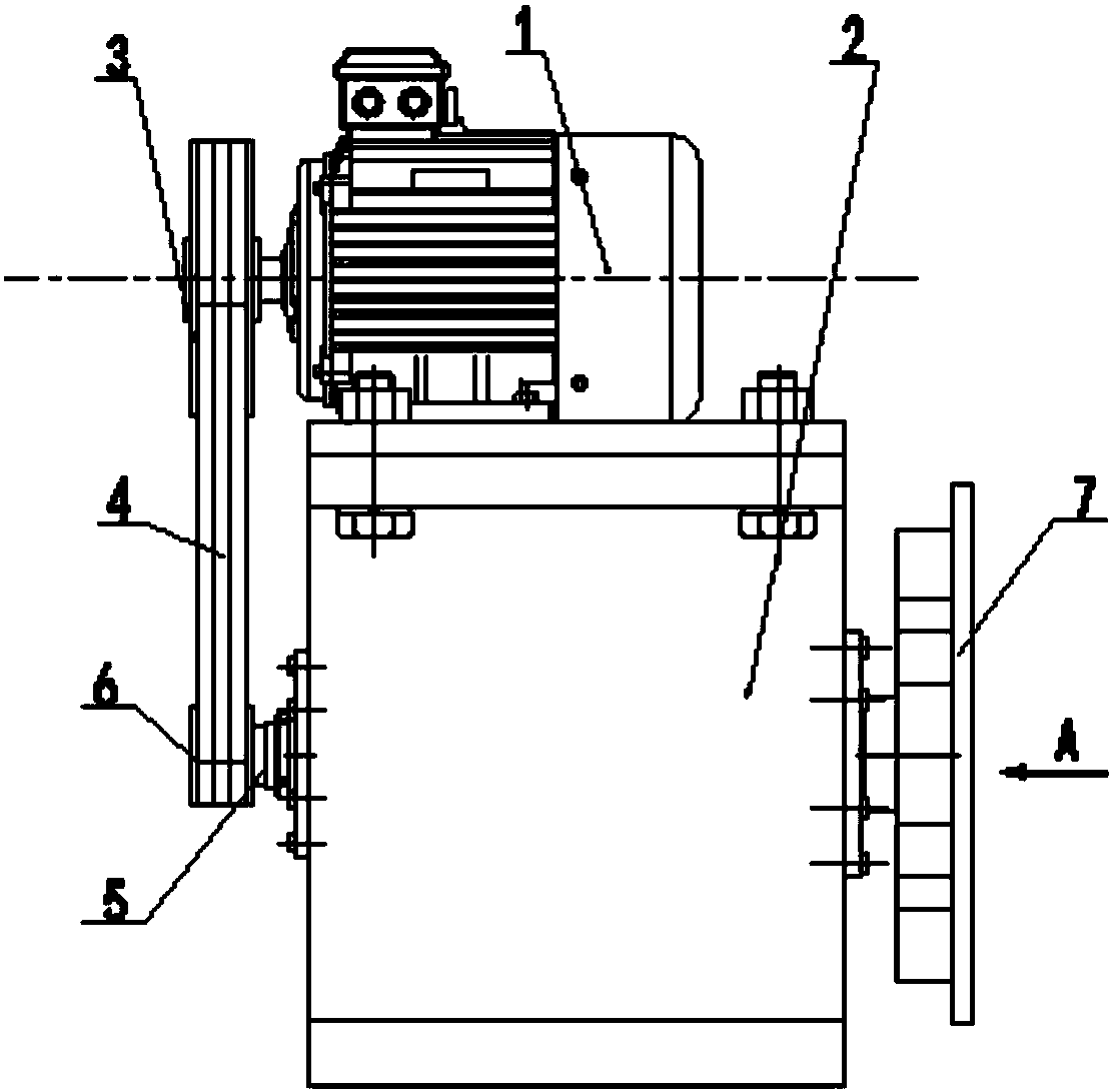
[0024] see figure 2 , the loading frequency control mechanism includes a box body 2 and a frequency conversion speed regulation three-phase asynchronous motor 1 arranged on the box body 2 and a main shaft 5 arranged in the box body 2, and the two ends of the main shaft 5 pass through the box body 2 and are exposed. Frequency conversion and speed regulation three-phase asynchronous motor 1 has a large pulley 3, the end of the main shaft 5 on the same side as the large pulley 3 has a small pulley 6, the large pulley 3 ...


PUM


Abstract

The invention discloses a fatigue break feeding machine for fixed workpiece fatigue load circumferential cyclic loading. A loading frequency regulating and controlling mechanism comprises a main shaftand a rotating chuck connected with the main shaft; a fatigue load loading mechanism comprises a first servo motor and a lead screw which are arranged on the rotating chuck, the first servo motor drives the lead screw to rotate, a nut is vertically installed on the lead screw, and a feeding die is movably installed on the nut; a workpiece clamping mechanism comprises a feeding opening and a discharging opening, the locations of the feeding opening and the discharging opening are separately provided with clamping assemblies, second servo motors of the clamping assemblies drive two-way lead screws to rotate, and each two-way lead screw is provided with two clamping pieces. A fatigue break principle is used, so that multiple fatigue crack sources are generated at the prefabricated stress gaps of rod and tube materials to enable the crack to quickly extend, and quick feeding of the rod and tube materials is achieved; and sections are kept smooth, end portions are free of deformation, wherein the fatigue load loading mechanism controls the displacement of the lead screws by the servo motors, and radial real-time adjustment of displacement amount is achieved.

Description

technical field [0001] The invention belongs to the technical field of blanking machines, and in particular relates to a fatigue fracture blanking machine which is subjected to circumferential cyclic loading of workpieces without fatigue loads. Background technique [0002] The blanking of metal rods and tubes is widely used in the preparation processes of cold extrusion, die forging, metal chain pins, rolling bearing rollers, pin standard parts, shaft parts and bearing parts, etc., and in these blanking processes , The amount of blanking is huge. However, the traditional shearing, sawing and laser cutting and other emerging cutting and blanking methods have problems such as low material utilization rate, large blanking force, low production efficiency, high energy consumption, and poor section quality to varying degrees, which do not meet the requirements of green technology. manufacturing and precision manufacturing requirements. [0003] The traditional blanking methods...

Claims


Application Information

Patent Timeline
IPC IPC(8): B21D31/00B21D43/00
CPCB21D31/00B21D43/003
Inventor 赵仁峰周憬钰李言郑建明肖旭东刘彦伟杨振朝
Owner XIAN UNIV OF TECH
Why Eureka
Try Eureka