Manipulator for assembly

A technology of manipulators and suction cups, applied in the direction of manipulators, program-controlled manipulators, chucks, etc., can solve problems such as the inconvenience of rivet processing, and achieve the effects of improving processing efficiency, facilitating passage, and increasing intervals

Active Publication Date: 2018-06-01
重庆厚朴开物科技有限公司
View PDF5 Cites 5 Cited by
  • Summary
  • Abstract
  • Description
  • Claims
  • Application Information

AI Technical Summary

Problems solved by technology

[0004] The purpose of the present invention is to provide a manipulator for assembly, to solve the problem that

Method used


Image

  • Manipulator for assembly
  • Manipulator for assembly
  • Manipulator for assembly

Examples


Embodiment 1

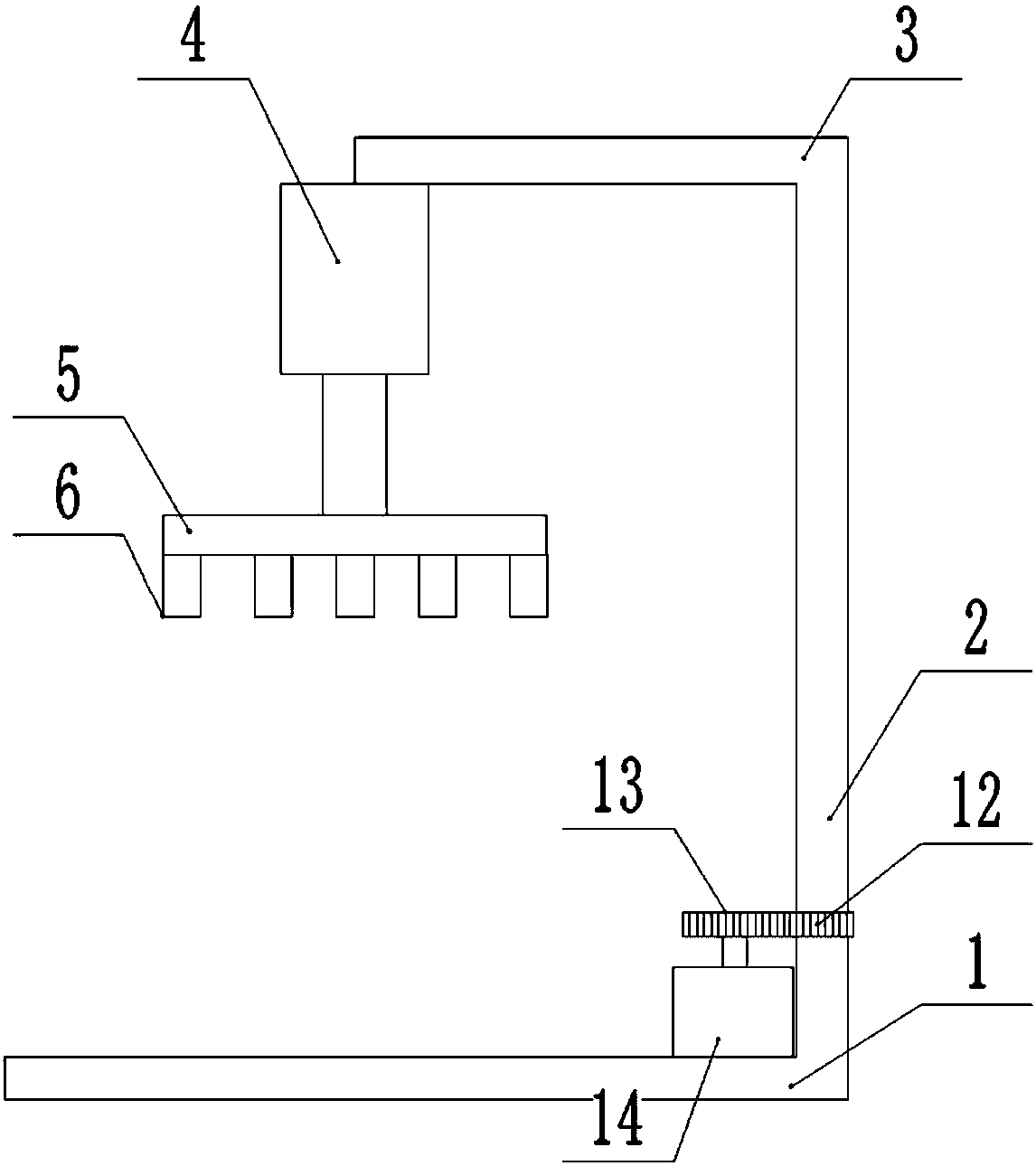
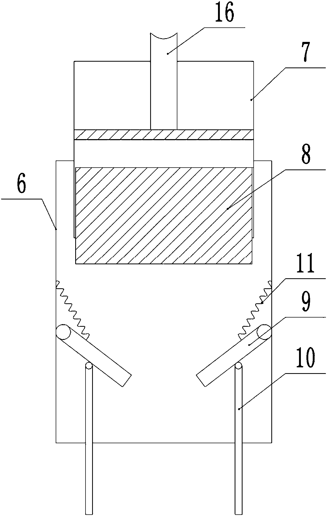
[0020] Such as figure 1 As shown, a manipulator for assembly includes a base 1, a bearing seat is installed on the right end of the base 1 through bolts, an interference-fit bearing is installed in the bearing seat, a support column 2 is installed in the bearing, and a toothed disc 12 is installed in the support. A servo motor 14 is installed on the base 1 at the right end of the support column 2, and a gear 13 is installed at the upper end of the rotating shaft of the servo motor 14. Rotate in the bearing seat; the top of the support column 2 is equipped with a cross bar 3, the left end of the cross bar 3 is connected with the first cylinder 4 with the piston rod downward through the bolt, and the lower end of the first piston rod of the first cylinder 4 is fixed with the bolt. Plate 5, the lower end of fixed plate 5 is equipped with a plurality of cylindrical suction cups 6 by bolts, preferably 25 in the present embodiment; figure 2 As shown, the upper end of the inner wal...

Embodiment 2

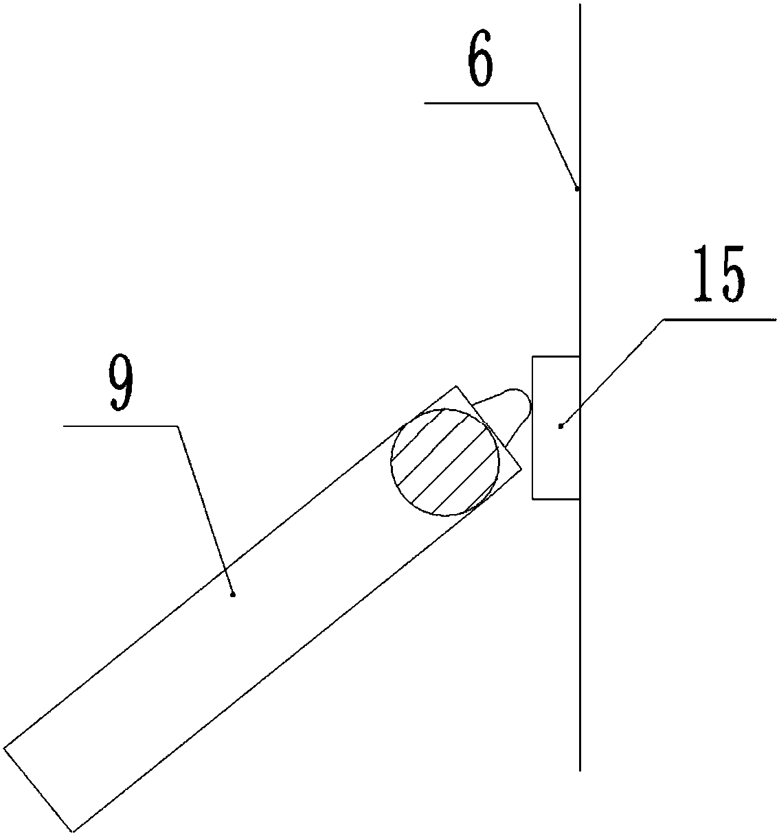
[0023] Such as image 3 As shown, on the basis of Embodiment 1, a self-locking switch 15 is installed at the joint between the baffle plate 9 and the inner wall of the suction cup 6, and the self-locking switch 15 is connected to the electromagnet 8 through a wire. When closed, the support rod 10 rotates to push the baffle plate 9 to rotate, and the baffle plate 9 rotates upwards to push the self-locking switch 15 to close to attract the rivet; when the rivet needs to be placed, the second cylinder 7 pushes the electromagnet 8 to move downward, and the electromagnet 8 Push baffle plate 9 to rotate downwards, and when baffle plate 9 rotates downwards, promote self-locking switch 15, the circuit of electromagnet 8 is disconnected, and rivet breaks away from electromagnet 8 after electromagnet 8 power-off, is placed on the installation place.


PUM


Abstract

The application of the invention belongs to the technical field of an assembling device, and particularly discloses a manipulator for assembly. The manipulator for assembly comprises a base; a supporting pillar rotationally connected with the base is arranged on the base, and a cross rod is arranged on the supporting pillar; a first cylinder is arranged on the cross rod, and the piston rod of thecylinder is connected with a fixing plate; the lower surface of the fixing plate is provided with multiple cylinder-shaped suction disks, upper ends of the suction disks are provided with second cylinders with downwards piston rods; lower ends of the second cylinders are provided with electromagnets which are in gliding and sealing connection with the inner wall of the cylinder; the middle parts of the suction disks are hinged with multiple baffles, and springs are connected between the baffles and the inner walls of the suction disks; the middle parts of the baffles are hinged with the supporting rod, and the lower end of the supporting rod is raised out of the suction disks when the baffles are under the non-stress state. The manipulator for assembly is mainly applied to absorb and transfer rivets, and solves the problems of many inconveniences in processing due to different rivet orientations during the using process of the rivets.

Description

technical field [0001] The invention belongs to the technical field of assembly equipment, and specifically discloses an assembly manipulator. Background technique [0002] Solid rivets are generally made of aluminum, copper, iron and other materials, and the surface treatment is white zinc plating; solid rivets can be widely used in knives, stationery, account books, locks, helmets, automobile hardware, luggage, baby carriages, automobile clutch steel plates, motorcycle accessories and household appliances. Class, through the use of solid rivets, provides great convenience for manufacturing. [0003] In the process of using solid rivets, due to the large amount of use, manual picking and placing of solid rivets not only wastes labor, but also has low efficiency in picking and placing rivets, which increases the cost of production and processing; and in the process of picking and placing rivets, it is necessary to manually adjust the rivets. Orientation brings a lot of inco...

Claims


Application Information

Patent Timeline
IPC IPC(8): B25J9/16B25J15/00B25J15/06B25J15/08
Inventor 李华
Owner 重庆厚朴开物科技有限公司
Why Eureka
Try Eureka