Wideband circular waveguide directional coupler used for measuring microwave power

A technology of directional coupler and microwave power, which is applied in the direction of waveguide devices, electrical components, connecting devices, etc., can solve the problems of large measurement errors, affecting the transmission of secondary waveguides, etc., and achieve reduced mutual influence, high isolation, and coupling degree fluctuations small effect

Active Publication Date: 2018-06-15
UNIV OF ELECTRONIC SCI & TECH OF CHINA
View PDF6 Cites 9 Cited by
  • Summary
  • Abstract
  • Description
  • Claims
  • Application Information

AI Technical Summary

Problems solved by technology

However, since the high-order mode cannot be transmitted in the standard rectangular waveguide, it will reflect back and forth in the non-standard rectangular sub-waveguide; and the hi

Method used


Image

  • Wideband circular waveguide directional coupler used for measuring microwave power
  • Wideband circular waveguide directional coupler used for measuring microwave power
  • Wideband circular waveguide directional coupler used for measuring microwave power

Examples


Embodiment Construction

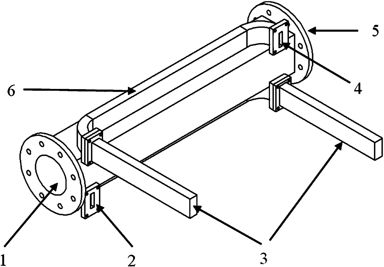
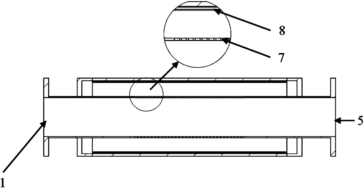
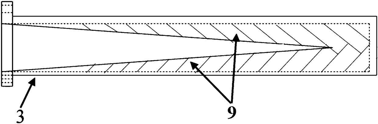
[0037]A kind of broadband circular waveguide directional coupler that is used for microwave power measurement, this directional coupler comprises: overmode circular waveguide (1) (i.e. main waveguide), double-arm secondary waveguide; Said double-arm secondary waveguide includes upper arm secondary waveguide and The lower wall auxiliary waveguide, the upper arm auxiliary waveguide or the lower wall auxiliary waveguide include: a non-standard rectangular waveguide (6), two non-standard over-modulated rectangular E-bend waveguides (2), and an absorption load (3); The modulus rectangular E-bend waveguide is arranged at both ends of the non-standard rectangular waveguide respectively, and is connected with the non-standard rectangular waveguide, and one of the non-standard over-modulated rectangular E-bend waveguides is connected to the absorbing load (3); the non-standard rectangular waveguide of the upper arm auxiliary waveguide The non-standard rectangular waveguides of the waveg...


PUM

PropertyMeasurementUnit
Bending angleaaaaaaaaaa

Abstract

The invention discloses a wideband circular waveguide directional coupler used for measuring a microwave power, and relates to the technical field of a microwave/millimeter-wave device. Compared witha traditional over-mode circular waveguide directional coupler, the wideband circular waveguide directional coupler has the advantages that a novel non-standard over-mode rectangular waveguide is introduced to substitute a standard rectangular waveguide in the traditional over-mode circular waveguide direction coupler, the cutoff wave number of a fundamental mode TE10 is changed by adjusting the size of the non-standard over-mode rectangular waveguide, so that the cutoff wave number of the fundamental mode TE10 of the non-standard over-mode rectangular waveguide is same as the cutoff wave number of a working mode TEmn in the over-mode waveguide, a propagation (phase) constant of the TE10 mode at an arbitrary frequency point is same as a propagation constant of the working mode TEmn, a forward wave of the coupler can conform to the same-direction superpose condition at the arbitrary frequency point, and the purposes of expanding the working bandwidth of the over-mode circular polarization directional coupler and reducing fluctuation of in-band coupling degree are achieved.

Description

technical field [0001] The invention relates to the technical field of microwave and millimeter wave devices, in particular to a circular waveguide structure for propagating and measuring high-power microwave and millimeter waves output by high-power microwave and millimeter-wave sources such as cyclotron traveling wave tubes and klystrons. Background technique [0002] The directional coupler is a microwave and millimeter-wave device widely used in the field of microwave and millimeter-wave measurement. Its main function is to accurately sample the high-power signals transmitted in the microwave and millimeter-wave systems, and couple a small part wave signal, in order to perform time-domain envelope monitoring, power measurement and spectrum measurement on the high-power signal transmitted in the system through measuring instruments such as oscilloscopes, small power meters, and spectrum analyzers. [0003] Most traditional high-power microwave systems use rectangular wave...

Claims


Application Information

Patent Timeline
IPC IPC(8): H01P5/18H01P1/26
CPCH01P1/26H01P5/182
Inventor 徐勇李洋孙淼彭廷会王兆栋罗勇
Owner UNIV OF ELECTRONIC SCI & TECH OF CHINA
Why Eureka
Try Eureka