An over-modulated circular waveguide broadband directional coupler and its design method

A technology of over-molded circular waveguide and directional coupler, which is applied in the direction of waveguide devices, electrical components, connecting devices, etc., and can solve problems such as poor directivity or isolation, narrow operating frequency band, and large fluctuations in in-band coupling. Achieve the effects of small fluctuations in coupling degree, wide operating frequency, improved operating bandwidth and isolation

Active Publication Date: 2017-07-11
UNIV OF ELECTRONICS SCI & TECH OF CHINA
View PDF2 Cites 2 Cited by
  • Summary
  • Abstract
  • Description
  • Claims
  • Application Information

AI Technical Summary

Problems solved by technology

[0005] In order to overcome the narrow working frequency band of the traditional overmode circular waveguide directional coupler (the relative bandwidth is generally less than 10%), the large fluctuation of the coupling degree in the band (the fluctuation of the coupling degree between some frequency points in the working frequency band is greater than 5dB), the directivity Or the problem of poor isolation (the directivity of the working frequency band is generally less than 20dB), the present invention proposes a new type of over-modulated circular waveguide broadband directional coupler

Method used


Image

  • An over-modulated circular waveguide broadband directional coupler and its design method
  • An over-modulated circular waveguide broadband directional coupler and its design method
  • An over-modulated circular waveguide broadband directional coupler and its design method

Examples


Embodiment

[0031] This embodiment provides an over-mode circular waveguide broadband directional coupler operating in the Ka band and TE01 mode, and its technical specifications are as follows:

[0032] Main waveguide working mode: TE 01 mold;

[0033] Working frequency band: Ka band, namely 26.5GHz-40GHz;

[0034] Standard rectangular waveguide model: BJ320, wide side size: 7.112 mm, narrow side size: 3.556 mm;

[0035] Coupling degree: -40dB; isolation degree (directivity): 20dB; in-band coupling degree fluctuation: ≤±1dB.

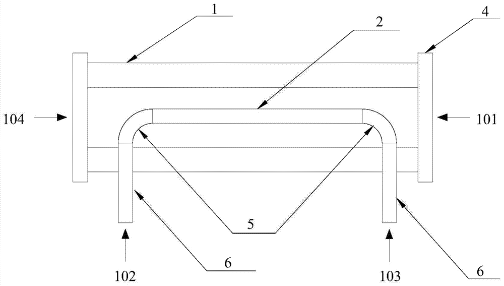
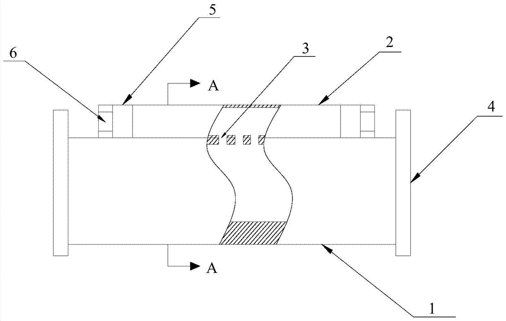
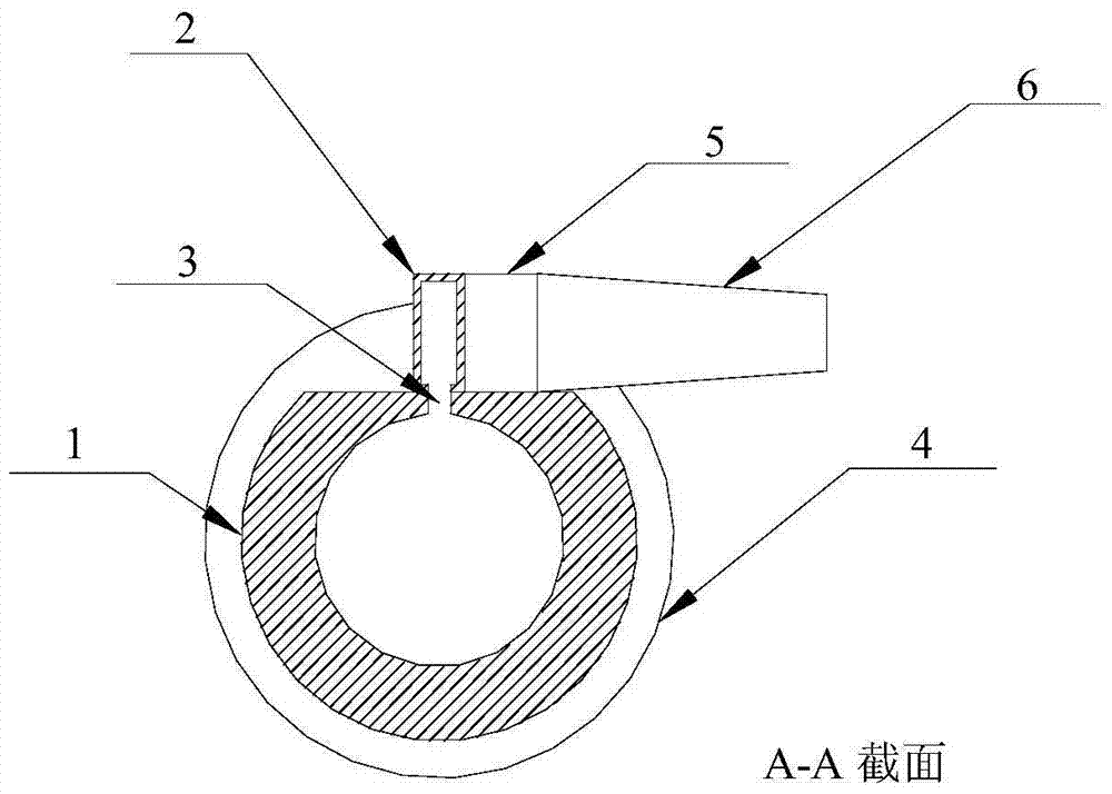
[0036] The structure of the over-mode circular waveguide broadband directional coupler provided in this embodiment is as follows figure 1 , figure 2 with image 3 As shown, the main structure and its specific dimensions are as follows:

[0037] 1 is an over-mode circular waveguide with an inner radius of 16 mm and a length of 220 mm;

[0038] 2 is a non-standard over-mode rectangular waveguide, the wide side size is 13.11 mm, and the narrow side size is 3.556 mm;

[0039] 3 i...


PUM


Abstract

The invention provides a novel over-mode circular waveguide broadband directional coupler and a design method thereof. The invention introduces a non-standard over-mode rectangular waveguide to replace the standard rectangular waveguide in the traditional over-mode circular waveguide directional coupler; by adjusting the size of the non-standard over-mode rectangular waveguide to change the cut-off wavenumber of its fundamental mode TE10 mode, the non-standard The cut-off wavenumber of the fundamental mode TE10 mode of the over-mode rectangular waveguide is the same as that of the working mode TEmn mode in the over-mode circular waveguide, so that the propagation constant of the TE10 mode at any frequency point is the same as that of the working mode TEmn, thus making the coupling The forward wave of the waveguide can meet the superposition condition in the same direction at any frequency point, so as to achieve the purpose of expanding the working bandwidth of the overmodulated circular waveguide directional coupler and reducing the fluctuation of the coupling degree in the band.

Description

Technical field [0001] The invention relates to the technical field of microwave and millimeter wave devices, in particular to an over-mode circular waveguide broadband output directional coupler and a design method thereof. Background technique [0002] The directional coupler is a microwave and millimeter wave device widely used in the field of microwave and millimeter wave measurement. Its main function is to accurately sample the high-power signal transmitted in the microwave and millimeter wave system, and couple a small part of the microwave, millimeter wave Wave signal in order to perform time-domain envelope monitoring, power measurement, spectrum measurement, etc. on high-power signals transmitted in microwave and millimeter wave systems through measuring instruments such as oscilloscopes, low-power meters, and spectrum analyzers. [0003] Most traditional high-power microwave systems use rectangular waveguides as transmission lines, and the matching directional couplers g...

Claims


Application Information

Patent Timeline
Patent Type & Authority Patents(China)
IPC IPC(8): H01P5/18
Inventor 徐勇罗勇夏建波王丽邓学王建勋嫣然成永东胥麟
Owner UNIV OF ELECTRONICS SCI & TECH OF CHINA
Why Eureka
Try Eureka