Electrooptical modulator based on phase-change material

A technology of electro-optic modulators and phase-change materials, which is applied in the fields of instruments, optics, nonlinear optics, etc., can solve the problems of undisclosed electro-optic modulators, etc., and achieve the effects of easy on-chip integration, simple manufacture, and reduced device size

Inactive Publication Date: 2018-07-13
NINGBO UNIV
View PDF3 Cites 16 Cited by
  • Summary
  • Abstract
  • Description
  • Claims
  • Application Information

AI Technical Summary

Problems solved by technology

However, there are no relevant research reports on electro-opti

Method used


Image

  • Electrooptical modulator based on phase-change material
  • Electrooptical modulator based on phase-change material

Examples


specific Embodiment

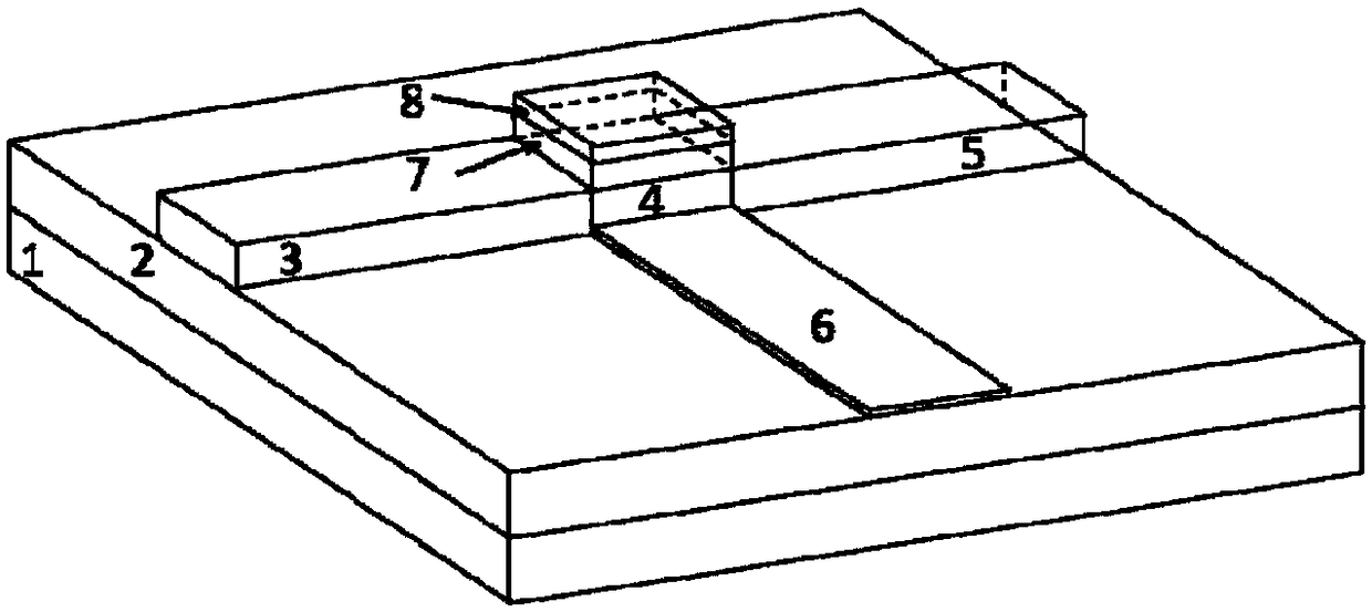
[0021] An electro-optic modulator based on phase-change materials, including an SOI substrate, consists of figure 1 As shown, the SOI substrate is provided with an input waveguide 3, a hybrid waveguide and an output waveguide 5 connected in the horizontal direction, and the hybrid waveguide is composed of a silicon waveguide layer 4, a phase change material GST layer 7 and a copper electrode layer 8 from bottom to top. superimposed.

[0022] In this specific embodiment, the SOI substrate includes a silicon substrate 1 with a thickness of 250nm and a silicon dioxide layer 2 with a thickness of 2um. The silicon dioxide layer 2 is arranged on the upper surface of the silicon substrate 1, and the input waveguide 3. The silicon waveguide layer 4 and the output waveguide 5 are arranged on the upper surface of the silicon dioxide layer 2 . The thickness of the input waveguide 3 and the thickness of the output waveguide 5 are both 250nm and the width is 400nm. The hybrid waveguide h...


PUM

PropertyMeasurementUnit
Thicknessaaaaaaaaaa
Thicknessaaaaaaaaaa
Widthaaaaaaaaaa

Abstract

The invention discloses an electrooptical modulator based on a phase-change material. The electrooptical modulator comprises an SOI substrate; the electrooptical modulator is characterized in that aninput waveguide, a mixing waveguide and an output waveguide connected in sequence are arranged on the SOI substrate in the horizontal direction, the mixing waveguide is formed by laminating a siliconwaveguide layer, a phase-change material GST layer and a copper electrode layer from bottom to top in sequence, the SOI substrate comprises a layer of silicon substrate body with the thickness of 250nanometers and a silicon dioxide layer with the thickness of 2 micrometers, the thicknesses of the input waveguide and the output waveguide are both 250 nanometers, the widths of the input waveguide and the output waveguide are both 400 nanometers, the thickness of the mixing waveguide is 290 nanometers, the width of the mixing waveguide is 400 nanometers, and silicon thin film with the thicknessof 10 nanometers is formed at one side of the silicon waveguide layer through selective erosion. The electrooptical modulator has the advantages that the size is small, on-substrate integration is facilitated, the energy consumption is low, the working bandwidth is large, the modulating depth is large, and the inserting loss is low.

Description

technical field [0001] The invention relates to an electro-optic modulator, in particular to an electro-optic modulator based on phase-change materials. Background technique [0002] With the continuous improvement of people's requirements for information processing speed, data transmission rate, and data storage capacity, the information network is growing at an explosive rate. In order to meet the needs of large-capacity and ultra-high-speed information interconnection, electro-optical signal processing devices with superior performance are often required. Electro-optic modulator, as the core device to realize the conversion of information between electrical signal and optical signal in optical communication transmission, has broad development and application prospects, and has aroused great interest of researchers. Existing silicon-based electro-optic modulators use the plasmonic dispersion effect of highly doped silicon or the Fermi level regulation of graphene to modul...

Claims


Application Information

Patent Timeline
IPC IPC(8): G02F1/00G02F1/01
CPCG02F1/0009G02F1/011G02F1/0113
Inventor 徐培鹏于增辉宋以鹏吕业刚张巍吴越豪
Owner NINGBO UNIV
Why Eureka
Try Eureka