Magneto-resistive devices

a magneto-resistive and resistance technology, applied in the field of magneto-resistive devices, can solve the problems of reduced s/n ratio, increased resistance, and accompanied by reduced resistance, and achieve the effect of high resistance change ratio, adequate control of electrical resistance, and increased outpu

Inactive Publication Date: 2005-07-12
HITACHI LTD
View PDF11 Cites 59 Cited by
  • Summary
  • Abstract
  • Description
  • Claims
  • Application Information

AI Technical Summary

Benefits of technology

[0020]The above-mentioned magneto-resistive device, magnetic head, magnetic recording device, and magnetic memory are characterized by a high ratio of change in resistance in response to an applied magnetic field, an adequately controlled electrical resistance, and an increased output, which result from the adequate film structure and adequate material selection for the magneto-resistive device.

Problems solved by technology

This poses some problems (such as noise and reduced S / N ratio) when it is used for a reproducing head or a magnetic field sensor.
Unfortunately, reduction in resistance is accompanied by reduction in output.
Another problem with the TMR device is that it increases in resistance as its surface area decreases.
In other words, a CPP-GMR device has too low a resistance to be applied to a magnetic reproducing device.
Moreover, the conventional GMR film has a high ratio of resistance change (several percent) in the CPP direction, but it has a very small output on account of the excessively low resistance.

Method used


Image

  • Magneto-resistive devices
  • Magneto-resistive devices
  • Magneto-resistive devices

Examples


example 1

[0082]A magnetic film containing Fe3O4 as a half-metal magnetic material was formed by RF sputtering on a substrate of glass, magnesium oxide, GaAs, AlTiC, SiC, Al2O3, SiO2, or the like.

[0083]The RF sputtering was carried out under the following conditions:[0084]Target: sintered body of Fe3O4 [0085]Atmosphere: argon at about 1-0.1 Pa[0086]Power: 50-150 W[0087]Maximum degree of vacuum achieved: lower than 5×10⁻³ Pa[0088]Rate of film growth: less than 0.1 Å / s

[0089]It was found that the Fe3O4 film can also be formed very slowly at a growth rate of 0.1-0.01 Å / s by molecular beam epitaxy (MBE), with oxygen being admitted into the atmosphere while Fe is being deposited.

[0090]The Fe3O4 film formed directly on the above-mentioned substrate varies in saturation magnetization depending on the substrate temperate, from less than 0.1 tesla (at room temperature) to 0.2-0.3 tesla (at 400° C.). These values are rather low for the single layer of Fe3O4.

[0091]The Fe3O4 film formed in this manner was...

example 2

[0100]It is important to see if an improvement is made over the conventional GMR in magnetoresistance effect when a half-metal material is bonded to another magnetic material, with a spacer interposed between them. This problem was attacked by calculating the bond at the interface with the help of a model based on electron transport. As shown in FIG. 5, the model consists of Fe3O4 (502), spacer (503), and CoFe (504) in consideration of the fact that electrons greatly transmit from one electron orbital to another. (In this model, s-electrons are assumed for 503 and 504.) The interface state density DL(R) in the left (right) electrode is represented by the formula (2) below, in which C denotes conductance and T denotes transmission rate.

C=T DLDR  (2)

[0101]In this model, the electron state is assumed to have the junction of electron density distribution as shown in FIG. 6. This electron density distribution is based on the simplified result obtained from band calculations by the first...

example 4

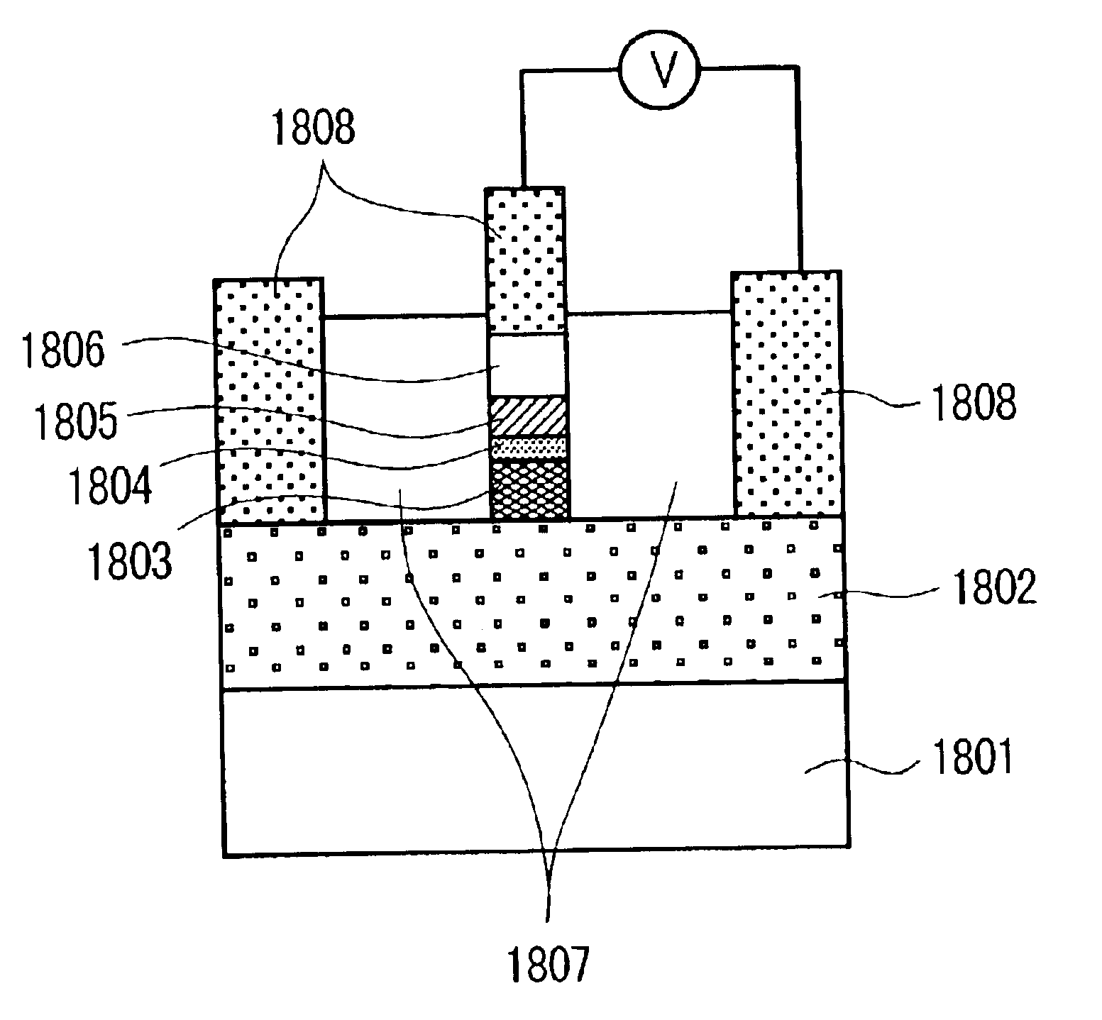
[0125]Samples of magnetoresistive devices of CPP-GMR structure composed of layers, as shown in FIGS. 20 and 21, were prepared. The layer is made up of the materials shown in FIGS. 8, 9, 10, 11, 12, and 15. Characteristic properties required of the PP-GMR film are:

(a) Sheet resistivity and area product RA no higher than 1 Ω·μm2 (depending on the device area).

(b) Ratio of change in magnetoresistance no lower than 2%.

(c) Coercive force of magnetic material.

[0126]The sheet resistivity and area product (RA) is calculated for the device measuring 120×120 nm in which an oxide magnetic material (such as Fe3O4) is used as the half-metal. A layered structure is assumed which consists of a noble metal layer (2005, 2106), a pinned layer (2006, 2105) containing an oxide half-metal, a spacer (2007, 2104) containing a noble metal, and a free layer (2008, 2103). The sample has a layered structure of Pt (10 nm), Fe3O4 (varied), Au (3 nm), and Fe3O4 (5 nm). The resistivity of Fe3O4, Pt, and Au were 3...


PUM

PropertyMeasurementUnit
surface areaaaaaaaaaaa
Tcaaaaaaaaaa
temperaturesaaaaaaaaaa

Abstract

A magneto-resistive device has a high reproducing output and is suitable for use as a CPP-GMR device. The magneto-resistive device has a first magnetic layer, a second magnetic layer, and a non-magnetic spacer formed between the first and second magnetic layers. The first magnetic layer contains a magnetic material whose conduction electrons belong to a first energy band, and the second magnetic layer contains a magnetic material whose conduction electrons belong to a second energy band. The first and second energy bands are attributable to orbitals of the same kind, thereby increasing the ratio of change in magnetoresistance and adjusting the electric resistance.

Description

BACKGROUND OF THE INVENTION[0001]The present invention relates to a magneto-resistive device, and to any component, such as a magnetic head, a magnetic recording device, and a magnetic memory, which is provided with said magneto-resistive device.[0002]Magnetic recording-reproducing devices have recently exhibited a significant improvement in recoding density. They are provided with a magnetic recording-reproducing head which requires both a high recording performance and a high reproducing performance.[0003]What is particularly required of magnetic recording heads is technical innovation for (1) a higher sensitivity, (2) a smaller track width, and (3) a smaller reproducing gap.[0004]Higher sensitivity leads to higher recording density. A recording density of the order of 1-10 Gb / in2 relies on the anisotropic magneto-resistive effect (AMR), and a recording density of the order of 10-20 Gb / in2 relies on the giant magneto-resistive effect (GMR), which gives a higher sensitivity. Moreov...

Claims


Application Information

Patent Timeline
Patent Type & Authority Patents(United States)
IPC IPC(8): G01R33/06G01R33/09H01F10/00G11C11/15G11B5/39H01F10/32H01L27/14G11C11/02H01L29/66H01L43/00H01L29/82H01L27/105H01L29/84H01L43/10H01L43/08H01L21/8246
CPCG11B5/3903H10B61/22H10N50/85H10N50/10
Inventor TAKAHASHI, HIROMASAHAYAKAWA, JUNSOEYA, SUSUMUITO, KENCHI
Owner HITACHI LTD
Why Eureka
Try Eureka