Optical deflector

a technology of optical deflector and optical frame, which is applied in the field of optical deflector, can solve the problems of affecting the operation of the optical deflector, the overall size of the module becomes large, and the loss of the advantages of the mems device, such as being small in size and having high functionality, and achieves stable deflection and scanning performance. , the effect of reducing the abnormal vibration of the mirror and reducing the abnormal vibration of the movable fram

Active Publication Date: 2009-07-16
STANLEY ELECTRIC CO LTD
View PDF2 Cites 59 Cited by
  • Summary
  • Abstract
  • Description
  • Claims
  • Application Information

AI Technical Summary

Benefits of technology

[0027]In the optical deflector of the sixth aspect, one pair or two pairs of the inner first piezoelectric actuators are installed across the mirror, and the mirror can be rotarily driven by the inner first piezoelectric actuators around the first axis. Furthermore, independently and simultaneously one or two pairs of the second piezoelectric actuators are installed across the movable frame, the movable frame as well as the mirror and the first actuators can be integrally rotarily driven by the second piezoelectric actuators around the second axis. This way, the mirror can be driven rotarily about two axes, and the stable deflection and scanning performance can be achieved in the two directions.
[0028]In this case, because of the first imp

Problems solved by technology

Because such an optical deflector has movable parts (torsion bars, piezoelectric actuators), the optical deflector may malfunction due to external vibrations, or be damaged by external impacts.
But if one attempts to cover the module having the mounted optical deflector with a cushioning material, the overall size of the module becomes large, and the advantages of MEMS devices, such as being small in size and having high functionality, would be lost.
However, because the optical deflector has movable parts, the area of the fixing frame (an area for gluing the cushioning material) relative to the entire bottom surface of the device is limited, and therefore, it is difficult to obtain sufficient cushioning effects against the external vibrations and impacts.
Moreover, in optical deflectors, the mirror is often damaged by a collision of the mirror to th

Method used


Image

  • Optical deflector
  • Optical deflector
  • Optical deflector

Examples


first embodiment

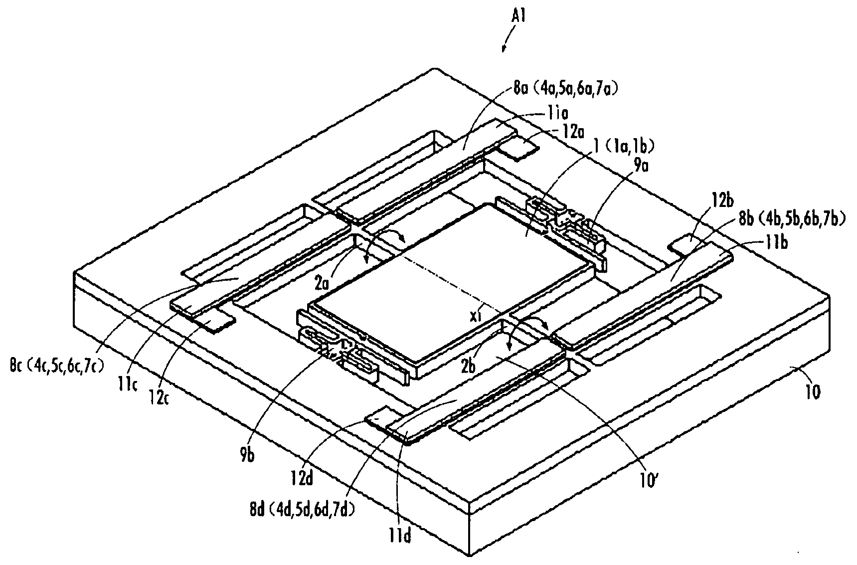
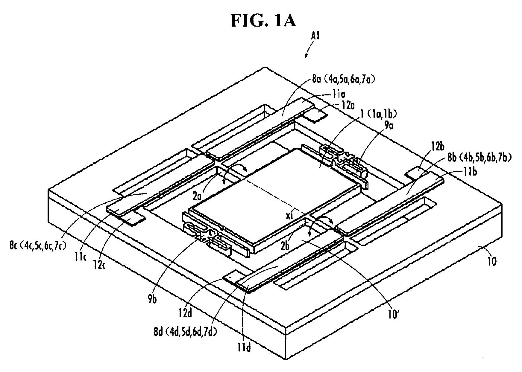
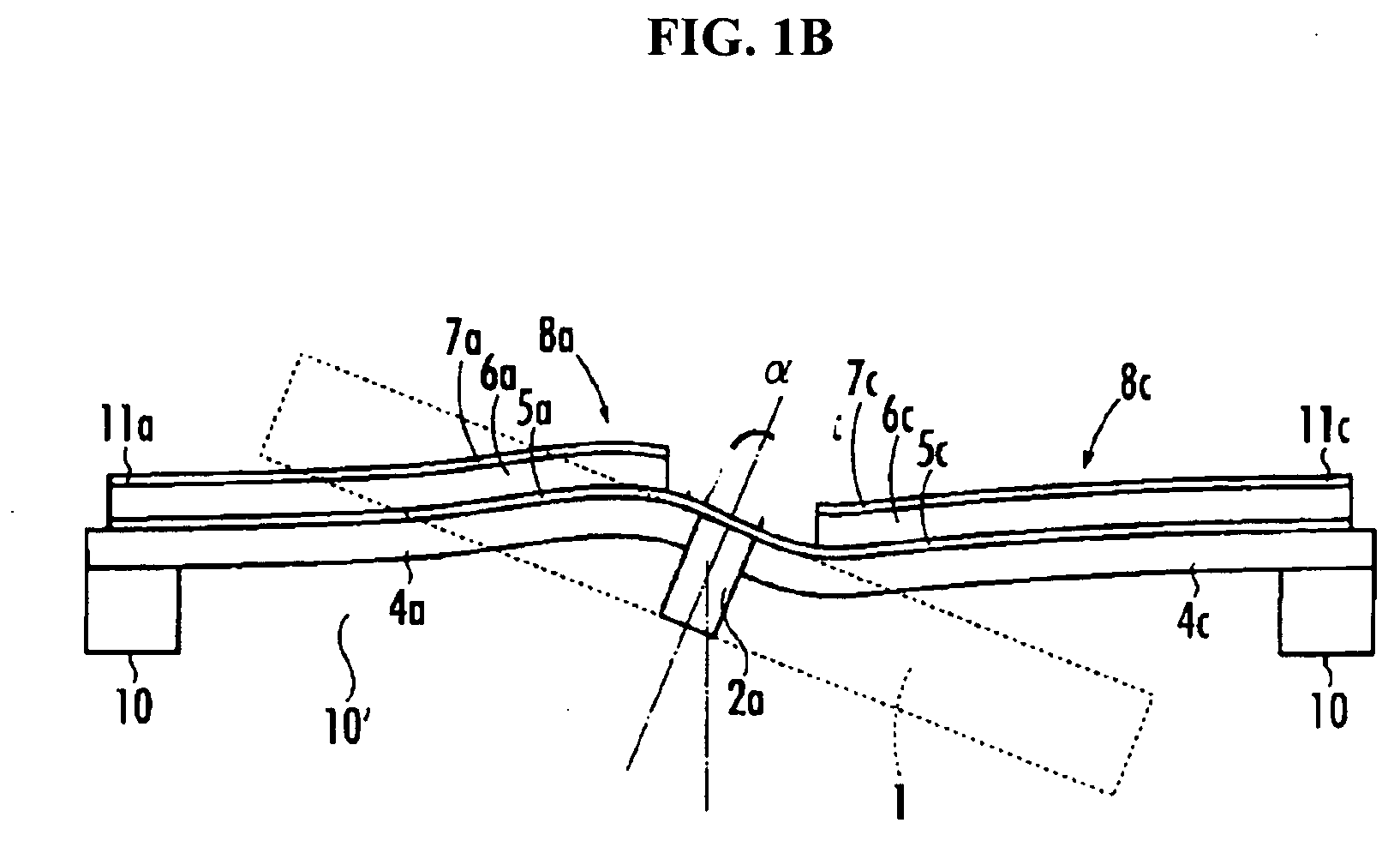
[0050]With reference to FIGS. 1A to 2H, an optical deflector according to a first embodiment of the present invention is described. FIG. 1A is a perspective view of the optical deflector A1 according to the present embodiment. FIGS. 2A-2H2 illustrate a manufacturing process of the optical deflector A1 of FIG. 1A.

[0051]As shown in FIG. 1A, the optical deflector A1 of the present embodiment includes a mirror 1 which reflects incoming light, torsion bars 2a, 2b which are connected to the mirror 1, piezoelectric actuators 8a-8d which rotarily drive the mirror 1 through the torsion bars 2a, 2b, a support 10 which supports the piezoelectric actuators 8a-8d, and impact attenuators 9a, 9b which are connected to the support 10.

[0052]The mirror 1 is rectangular in its shape, and a pair of torsion bars 2a, 2b extend outwardly from the center of respective sides of the mirror 1. The anchoring end of the torsion bar 2a is connected to the support 10 and the leading end is connected to the mirror...

second embodiment

[0100]A second embodiment of the present invention is described with reference to FIG. 3. FIG. 3 is a perspective view showing a configuration of optical deflector A2 of the second embodiment of the present invention. The optical deflector A2 of the present embodiment is equipped with additional two pairs of piezoelectric actuators in order to rotarily drive, as a unit, the mirror, the torsion bars, and two pairs of the piezoelectric actuators of the first embodiment.

[0101]The optical deflector A2 of the present embodiment includes a mirror 41 which reflects incident light, first torsion bars 42a, 42b connected to the mirror 41, two pairs of inner first piezoelectric actuators 48a-48d, movable frame 49 supporting the first piezoelectric actuators 48a-48d, second torsion bars 50a, 50b connected to the movable frame 49, two pairs of outer second piezoelectric actuators 51a-51d, and support 52 which supports the second piezoelectric actuators 51a-51d.

[0102]The mirror 41 is rectangular...

third embodiment

[0122]A third embodiment of the present invention is explained with reference to FIG. 4. FIG. 4 is a perspective view which shows a configuration of optical deflector A3 according to the third embodiment. The optical deflector A3 of the present embodiment is similar to the first embodiment except that the impact attenuators are different from those provided in the first embodiment. The same reference numerals are used to indicate the same or like elements as in the first embodiment, and explanations of the same or like elements that have been explained above are not repeated below.

[0123]As in the case of the impact attenuators 9a, 9b of the first embodiment, as shown in FIG. 4, impact attenuators 61a, 61b of the present embodiment are installed in a gap 10′ so as to be connected to the support 10 and to face the two opposing sides of the mirror 1 that are perpendicular to the other two opposing sides of the mirror 1 form which the torsion bars 2a, 2b extend outwardly. However, in th...


PUM


Abstract

An optical deflector includes a mirror having a reflective plane; a torsion bar extending outwardly from a side of said mirror; a support surrounding said mirror; a piezoelectric cantilever including a supporting body and a piezoelectric body formed on the supporting body, one end of said piezoelectric cantilever being connected to said torsion bar, the other end of the piezoelectric cantilever being connected to said support, said piezoelectric cantilever, upon application of a driving voltage to the piezoelectric body, exhibiting a bending deformation due to piezoelectricity so as to rotate said torsion bar, thereby rotarily driving said mirror through said torsion bar; and an impact attenuator connected to said support, the impact attenuator being disposed in a gap between said mirror and said support.

Description

BACKGROUND OF THE INVENTION[0001]1. Field of the Invention[0002]The present invention relates to an optical deflector for deflecting and sweeping a light beam such as a laser beam.[0003]2. Description of the Related Art[0004]Recently, an optical deflector, in which a mirror and piezoelectric actuators are formed integrally on a semiconductor substrate, has been proposed as a MEMS (micro electro mechanical systems) device using semiconductor processes and micro machining technology. In the optical deflector, one end of a piezoelectric actuator is linked to and supported by a frame part (a support part), and a torque, which is generated by an piezoelectric actuator, is transmitted to a torsion bar (an elastic beam) which is in turn connected to other end of the piezoelectric actuator, thereby rotarily driving a mirror attached to an end of the torsion bar. Advantages of such an optical deflector are: such an optical deflector is small in size, is simply structured, provides a large dr...

Claims


Application Information

Patent Timeline
IPC IPC(8): G02B26/08
CPCG02B26/105G02B26/0858B81B3/0051B81B7/0016
Inventor TANI, MASANAOYASUDA, YOSHIAKIAKAMATSU, MASAHIROAIMONO, TAKANORI
Owner STANLEY ELECTRIC CO LTD
Why Eureka
Try Eureka