Air assistance apparatus providing fast rise and fall of pressure within one patient's breath

a technology of air assistance apparatus and patient, which is applied in the direction of magnetic circuit rotating parts, machines/engines, shape/form/construction, etc., can solve the problems of 10 khz bandwidth, inability to operate correctly at high speed, and high cost of sensors, so as to achieve fast rise and fall, high rotation speed, and increase pressure

Active Publication Date: 2008-11-11
KONINKLJIJKE PHILIPS NV
View PDF21 Cites 59 Cited by
  • Summary
  • Abstract
  • Description
  • Claims
  • Application Information

AI Technical Summary

Benefits of technology

[0085]Another advantage of the invention is that, the high rotation speed and quick rise time and fall time also enables to use tubes of a smaller size. Historically CPAP and respiratory assistance devices are using 1.8 m long, 22 mm outside diameter tubing, because the pressure drop on those tubes are negligible (0.7hPA for 11 / s airflow). Pressure drops are happening during inspiration and, during expiration, pressure is increasing. In that case it is important that the pressure of the provided air does not change too much; this is the reason why 22 mm diameter tubes are used. The downsides of those tubing's are size and weight. It can be interesting to use smaller tubes given the reduced size of the apparatus. The downside of a reduced diameter tubing is the fact that significant pressure drops are occurring. Given the light weight of the impeller / rotor 2 combined with the efficiency of the motor driving system 36 and the load control of the power supply manager 29 allowing very fast and accurate accelerations / decelerations, the apparatus according to the present invention is able to compensate those pressure drops thus allowing the use of smaller tubing's (i.e. 15 mm outside diameters).
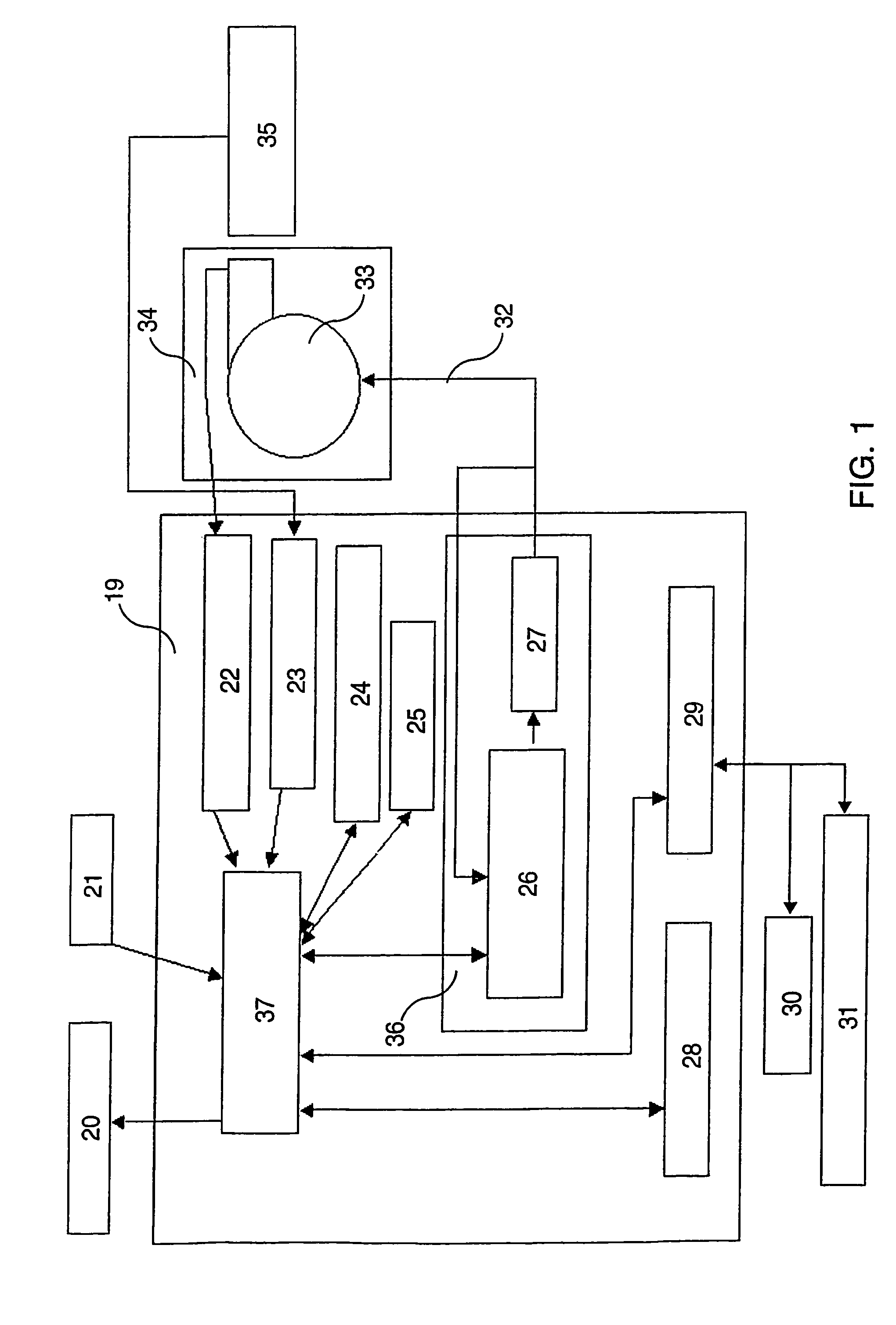
[0087]The apparatus has a two steps, strong recognition, process in order to prevent false start of the apparatus when the mask is not on the patient's face and to prevent starting a new treatment session. When the apparatus is started by the patient by using the keyboard, for example and as represented in FIG. 13 by using the start key, the blower 33 is kept turning at a very low speed, waiting for some activity on the mask pressure sensors 23. When an activity is detected, the apparatus is instantaneously trying to bring the pressure at the apparatus outlet 9 at a minimum starting pressure P0 of 4 hPa. This will guarantee that no CO2 rebreathing will occur. When this pressure is reached the estimation module 100 tries to identify at least one breath to start the treatment process according to the settings. When the mask is not applied against something, like a hand or the patient's face, no activity is detected. Then if a maximum time has been spent (the timeout is reached) since the start key is actuated, without detecting any activity, the blower is stopped. On the contrary, the apparatus keeps on waiting for an activity on the pressure sensors. When the mask is not applied correctly the pressure can not reach 4 hPa. Then if the timeout is reached the blower is stopped, on the contrary the apparatus tries again to detect some activity on the pressure sensors. When the mask is not applied on the patient's face no breath pattern is recognized. Then the blower is stopped if the timeout is reached. On the contrary the estimation module 100 waits to detect some activity on the pressure sensors. The timeout checking prevents the blower keeping turning on if the patients does not start the treatment and forget to start the blower.
[0088]Preferentially, the data of the pressures PM 112 and PB 114 which are sensed at the extremities of the tube and the data 116 of the tube coefficient KT enable the airflow computation 130. One formula that can be use to compute the airflow from these values is:Airflow3=(PM−PB) / KT
[0089]The following examples demonstrate the way the estimation module 100 modulates the pressure value PM to apply to the patient's mask.

Problems solved by technology

Standard sensors have usually a 10 kHz bandwidth and thus are not able to operate correctly at high speeds.
Higher speeds can be provided by using sensors with a higher bandwidth but those sensors are expensive and still have a speed limitation.
In fact the faster the rotor rotates the worse the detection is accurate, the less the motor is efficient.
Sometimes the system can even stall.
Because these problems of positioning and reliability, those air providing apparatus which are using these sensors do not use high speed motors.
Moreover, in the case of a CPAP that does not require pressure changes within a breath, to have a well regulated pressure at the patient interface, these apparatus are requiring the use of a 22 millimeters diameter tube as the pressure drop within such a tube is negligible but the use of a smaller tube will not guarantee the pressure regulation A within acceptable bounds.
The size of the impeller, the sensor positioning and attachments and the number of wires required increase the size of the blower and thus of the apparatus.
Furthermore the precise positioning of the sensors complicates the assembling of the motor implying an increase of the cost.
There are no means for sensing the motor current.
U.S. Pat. No. 5,977,737 does not disclose a way to determine the rotor's position.
This document thus does not provide any indication to obtain fast accelerations and decelarations within a patient's breath.

Method used


Image

  • Air assistance apparatus providing fast rise and fall of pressure within one patient's breath
  • Air assistance apparatus providing fast rise and fall of pressure within one patient's breath
  • Air assistance apparatus providing fast rise and fall of pressure within one patient's breath

Examples


example 1

Pressure Pm at Patient's Mask within a Breath

[0090]As represented in the FIG. 15 the pressure provided is not constant but is a function of time.

[0091]At time t1 the patient starts breathing in. Time t2 is defined when the absolute value of airflow starts to decrease within the inspiration phase or shows a fixed delay after t1. As the estimation module is calculating the derivative of the airflow function, it is able do determine this time for example when the derivative reaches zero. Time t3 is the start of expiration. Time t4 is defined when the absolute value of airflow starts to decrease within the expiration phase or shows a fixed delay after t3. Time t5 is the end of the breath step and the beginning of a next breath step.

[0092]In order to reduce the patient's lung effort the estimator increases the value of pressure PM from time t1 to t2. After time t2 as the absolute value of airflow is decreasing the estimation module decreases the pressure value. In the same way, to reduce...

example 2

Variations of the Average Pressure of Treatment as a Function Time According to Detected Events

[0098]In a preferential embodiment the average pressure of treatment within one breath, that is to say within one breathing step, can be modulated according to the events occurring, such as snoring or apneas or abnormal breathing patterns.

[0099]The apparatus will normally (no events detected)try to reduce the average pressure of treatment value, thus enhancing the patient comfort while breathing against the apparatus. The clinician set a minimum average pressure of treatment Ptmin and a coefficient NOEK expressed in hPa / s.

[0100]In the following example the terms AVP, are the average pressure of the pressure to patient's mask on one breath step. On FIG. 17, this average pressure as been noted PM, as the measurement is made on the first pressure sensor 6. As represented on FIG. 17, when no events are detected the average pressure of treatment value will follow the equation:

AVP(t)=MAX(AVP(t−ε...

example 3

Variations of the Slope SLH of the Value of Pressure PM Applied to the Patients Mask within a Breath

[0110]The slope coefficient of the pressure applied function of time within a breath can also be modulated according to time. In a preferential mode this coefficient remains constant on each single breath step (one inspiration and one expiration), but can be changed from one step to another.

[0111]The apparatus will try to reduce the slope coefficient SP, thus enhancing the patient comfort while breathing against the apparatus. The clinician set a minimum the slope coefficient SP, and a coefficient NSP expressed in hPa / s.

[0112]The events are detected the slope coefficient SP value will follow the equation:

SLH(t)=MAX(SLH(t−ε)−(NOES×ε),SLHmin)

ε being the sampling time, the MAX function is returning the greatest value of its two members.

[0113]The shape of the corresponding curve is like the one for average pressure in FIG. 17.

[0114]When an event is detected, a 3 steps process is initiated...


PUM


Abstract

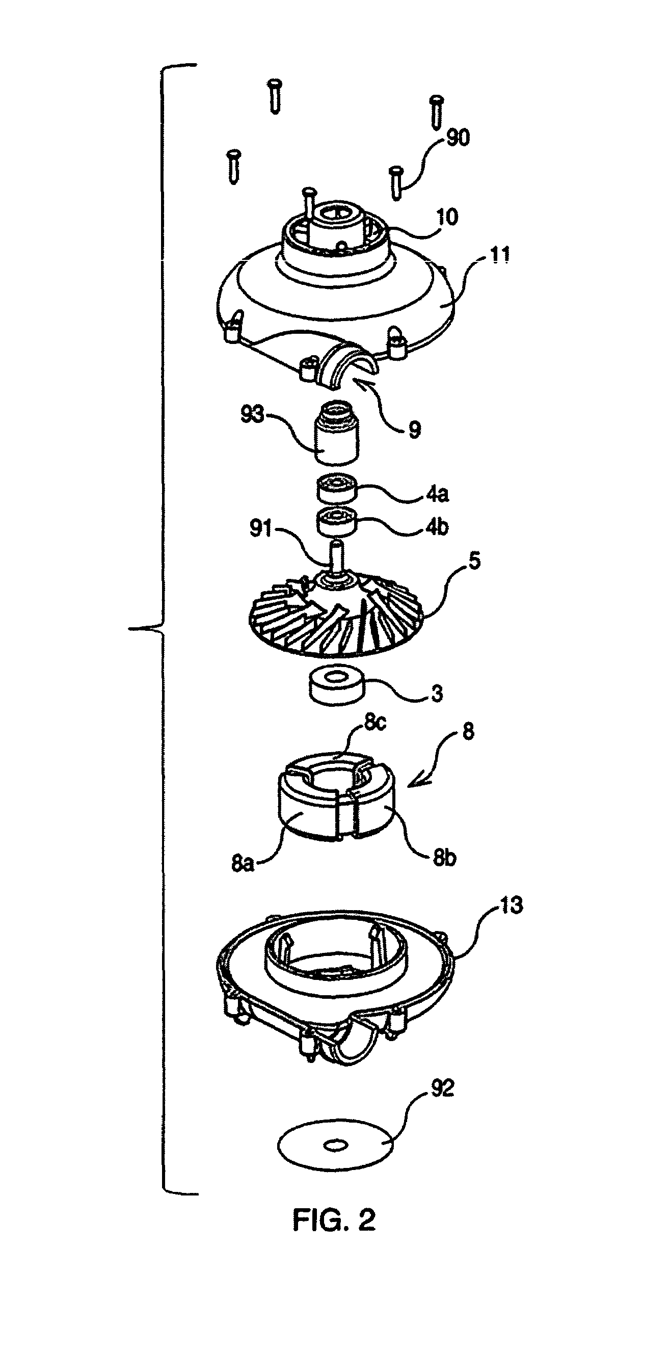
An apparatus to deliver air to a patient through a mask, including an air blower (33) where the impeller (5) is rotated by an electromotor including a rotor (3) and a stator (8), the stator having at least three sectors (8a, 8b and 8c), the rotation of the rotor being enabled by changes of the polarity of the sectors, each sector's polarity configuration constituting one step of the rotor's rotation, the apparatus including a driving unit (36) changing the sectors' polarity when the rotor is at its optimal position, so that the efficiency of the electromotor enables the blower to have fast accelerations and decelerations within one patient's breath step, the breath step consisting of one inspiration and one expiration.

Description

[0001]This application is a U.S. National Stage of International application PCT / IB03 / 01392, filed Mar. 10, 2003 and claims benefit of U.S. provisional application Ser. No. 60 / 362,441, filed Mar. 8, 2002.TECHNICAL FIELD[0002]The present invention concerns a medical apparatus to assist a patient respiration and more specifically an apparatus able to control the pressure of the air provided to the patient.BACKGROUND ART[0003]Some apparatus are used to provide patients with air. This is used in many treatments. More frequently it is used for patients with a breathing deficiency caused for example by the weakness of the breathing system or by obstructive apneas during the sleep. In those cases it is important to control the pressure of the air delivered to the patient. With respiratory insufficient patients, apparatus providing air at a higher pressure help to compensate the weakness of the patients lungs. In the case of patients suffering of sleep apneas, providing the air at a higher ...

Claims


Application Information

Patent Timeline
Patent Type & Authority Patents(United States)
IPC IPC(8): A61M16/00A62B7/00F16K1/08F16K31/02H02K1/22H02K21/12H02K5/16H02K7/08H02P6/08H02P23/00
CPCH02P6/085H02P23/0063H02P23/20A61M16/0069F04D17/16Y02B30/70F04D27/004
Inventor DELACHE, ALAINDELACHE, VERONIQUE
Owner KONINKLJIJKE PHILIPS NV
Why Eureka
Try Eureka