Light emitting apparatus

a technology of light-emitting apparatus and light-emitting tube, which is applied in the direction of lighting and heating apparatus, fixed installation, instruments, etc., can solve the problems of inability to meet the requirement to reduce the size of the light-emitting tube, the composition of the apparatus will be complicated, and the illumination intensity cannot be uniform

Inactive Publication Date: 2004-09-02
TOYODA GOSEI CO LTD
View PDF3 Cites 58 Cited by
  • Summary
  • Abstract
  • Description
  • Claims
  • Application Information

AI Technical Summary

Problems solved by technology

When a plurality of light emitting diode elements are disposed close to each other in order to enlarge the illumination area or to enhance the illumination intensity, lights from the light emitting diode elements are overlapped partially and, therefore, unevenness in illumination intensity occurs.
However, since each light emitting diod

Method used


Image

  • Light emitting apparatus
  • Light emitting apparatus
  • Light emitting apparatus

Examples


Embodiment Construction

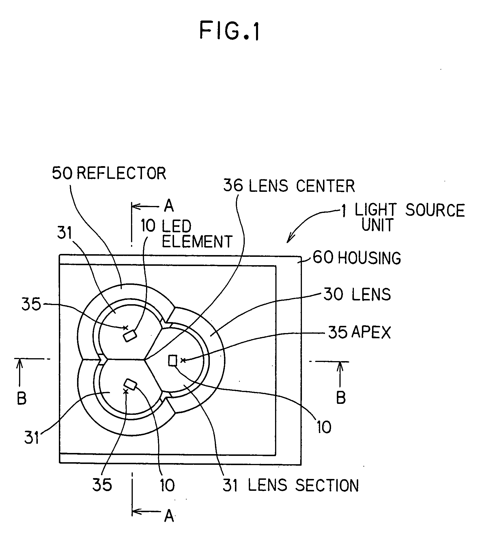
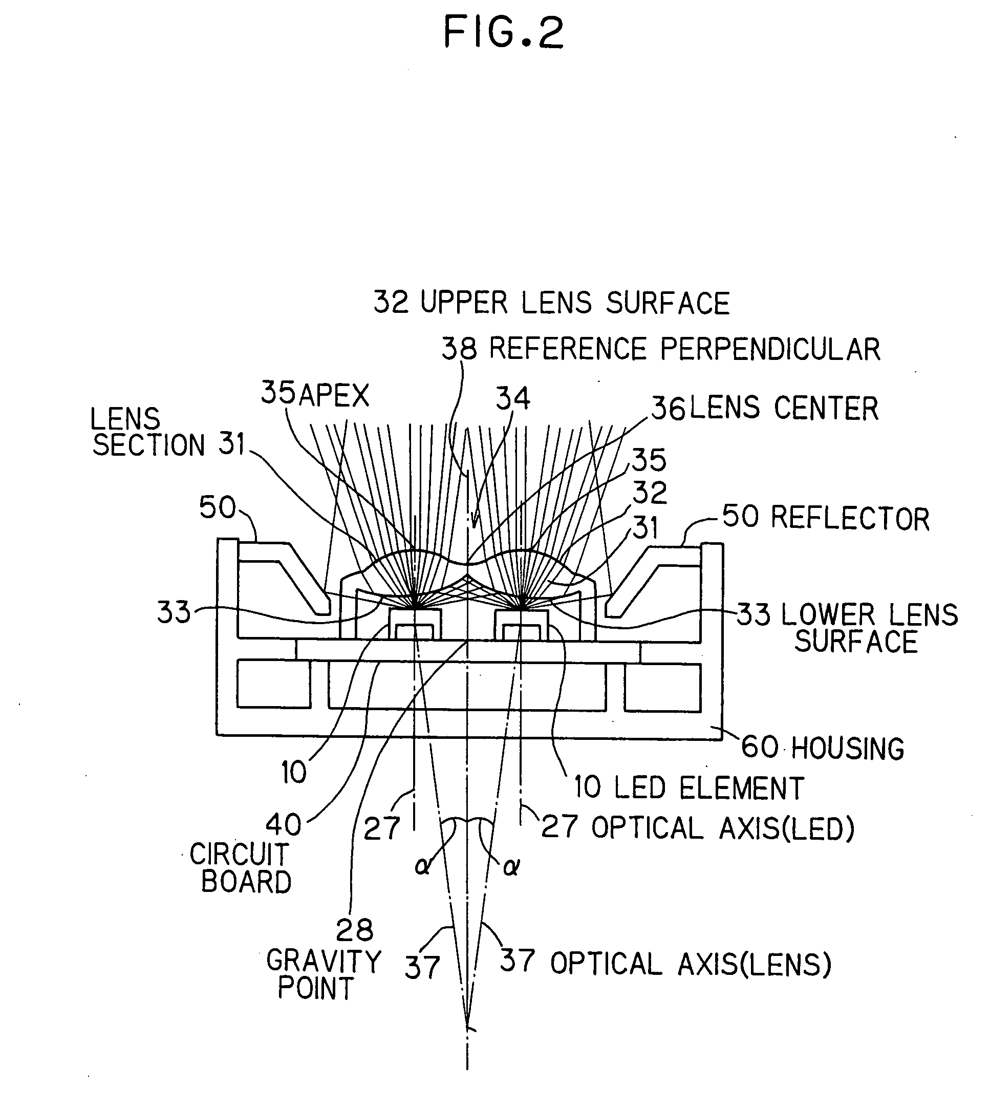
[0051] FIG. 1 is a top view showing a light source unit 1 in the preferred embodiment according to the invention. FIG. 2 is a cross sectional view cut along the line A-A in FIG. 1. FIG. 3 is a cross sectional view cut along the line B-B in FIG. 1. FIG. 4 is a schematic cross sectional view showing an LED element 10 used in the light source unit 1.

[0052] The light source 1 is composed of: a housing 60; surface mounted type light emitting diode elements 10 (hereinafter referred to as LED element); a lens 30; a circuit board 40; and a reflector 50. The LED element 10 is composed of an LED chip 11, a substrate 20, a reflector 21 and a sealing member 22 (See FIG. 4). Meanwhile, the LED element 10 includes a Zener diode (not shown) for anti-electrostatic.

[0053] FIG. 5 is a schematic cross sectional view showing the LED chip 11 used in the LED element 10. As shown, the LED chip 11 is composed of a sapphire substrate 12 and a plurality of layers formed on the sapphire substrate 12. It has a...


PUM


Abstract

A light emitting apparatus has: a plurality of surface mount device (SMD) type light emitting diode elements; a circuit board on which the plurality of SMD type light emitting diode elements are mounted; and a plurality of convex lenses each of which covers the light extraction side of corresponding one of the plurality of SMD type light emitting diode elements. The lens optical axis of at least one of the plurality of convex lenses does not coincide with an axis that passes through the center of corresponding one of the plurality of SMD type light emitting diode elements and is perpendicular to the circuit board.

Description

[0001] The present application is based on Japanese patent application No.2003-054776, the entire contents of which are incorporated herein by reference.[0002] 1. Field of the Invention[0003] This invention relates to a light emitting apparatus using a light emitting diode element. For example, a light emitting apparatus of the invention is used as illumination light source in vehicle.[0004] 2. Description of the Related Art[0005] Surface mount device (SMD) type light emitting diode elements are widely used as a light source such as illumination unit with limited installation space. For example, Japanese patent application laid-open No.6-103802 discloses a vehicle high mount stop lamp that a plurality of SMD type light emitting diode elements are arranged linearly. In this example, lens is disposed to cover each light emitting diode element, and light emitted from the light emitting diode element is converged by the lens function to enhance the directivity of light. On the other han...

Claims


Application Information

Patent Timeline
IPC IPC(8): F21S8/10F21V5/04F21W106/00F21Y101/02H01L33/30H01L33/58H01L33/60H01L33/62
CPCF21V5/04H01L33/58F21Y2101/02F21Y2115/10
Inventor NAWASHIRO, MITSUHIRO
Owner TOYODA GOSEI CO LTD
Why Eureka
Try Eureka