System for actively reducing radial vibrations in a rotating shaft, and method of operating the system to achieve this

a technology of radial vibration and system, which is applied in the direction of gearing control, support/enclosement/case, electric energy vehicles, etc., can solve the problems of high-quality material and expensive production process, vibrations are bending vibrations, and great static overdetermination

Inactive Publication Date: 2000-10-31
CONTINENTAL ISAD ELECTRONICS SYST GMBH & CO KG
View PDF128 Cites 64 Cited by
  • Summary
  • Abstract
  • Description
  • Claims
  • Application Information

AI Technical Summary

Benefits of technology

Yet different phase relationships are also possible (e.g., 190.degree. instead of 180.degree.), in order to diminish vibrations in other parts of the vehicle, which generally occur with a phase displacement.
If the shaft is exposed to forces which are directed opposite its radial velocity, energy will be withdrawn from its undesirable radial vibration -namely, the shaft performs work under the braking force of the active electromagnetic device. Consequently, the amplitude of the vibration decreases--the radial vibration is dampened.
it allows a very effective suppression or dampening of radial vibrations, especially of crankshafts;
because of the very effective vibration suppression / dampening, heavily loaded crankshafts can be created with lower expenditure / lower costs (namely, from less high-quality material and with less fabrication expense);
ii) With two or more active sectors, the additional degree of freedom allows free choice in the direction and magnitude of the radial force. Here, again, a torque is generally applied to the shaft.
Especially advantageous, the electric machine further serves to actively reduce rotational nonuniformities of the shaft by applying a rapidly varying torque to the shaft, for example, in opposite phase to the rotational nonuniformities. The rotational nonuniformities as well result chiefly from the gas and mass forces in an internal combustion engine.

Problems solved by technology

Because of the practically no-play mounting of the crankshaft in the radial direction, these vibrations are bending vibrations.
This requires, in particular, high-quality material and a costly production process (e.g., die forging).
This produces great static overdetermination.
This may produce resonance rises which can lead to fracture of the crankshaft.

Method used


Image

  • System for actively reducing radial vibrations in a rotating shaft, and method of operating the system to achieve this
  • System for actively reducing radial vibrations in a rotating shaft, and method of operating the system to achieve this
  • System for actively reducing radial vibrations in a rotating shaft, and method of operating the system to achieve this

Examples


Embodiment Construction

The purpose of the invention is to provide a different solution for the radial vibration problem of a shaft, especially the drive shaft of an internal combustion engine.

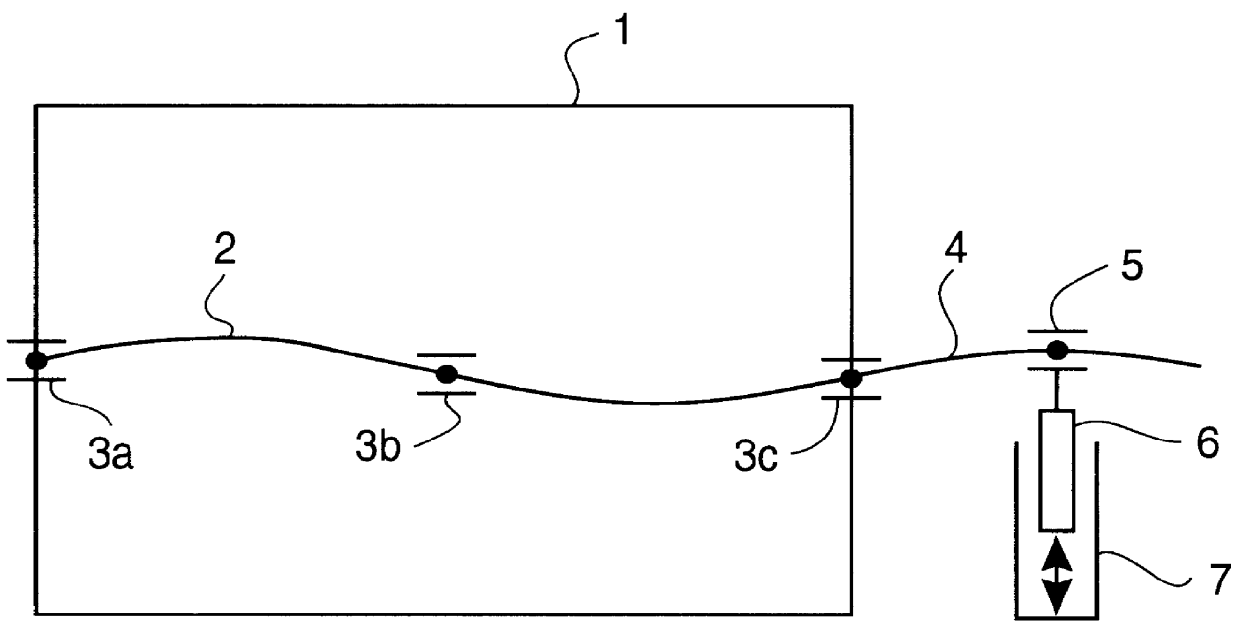
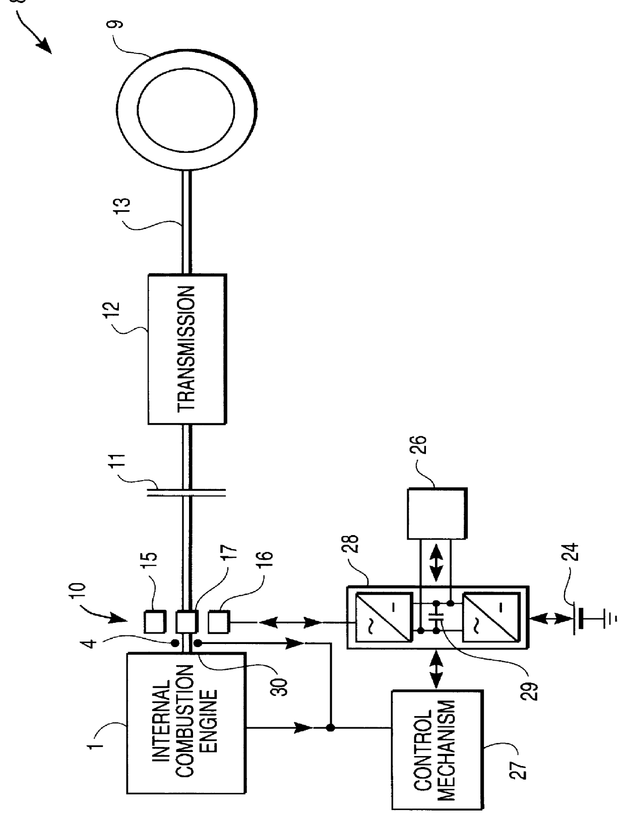
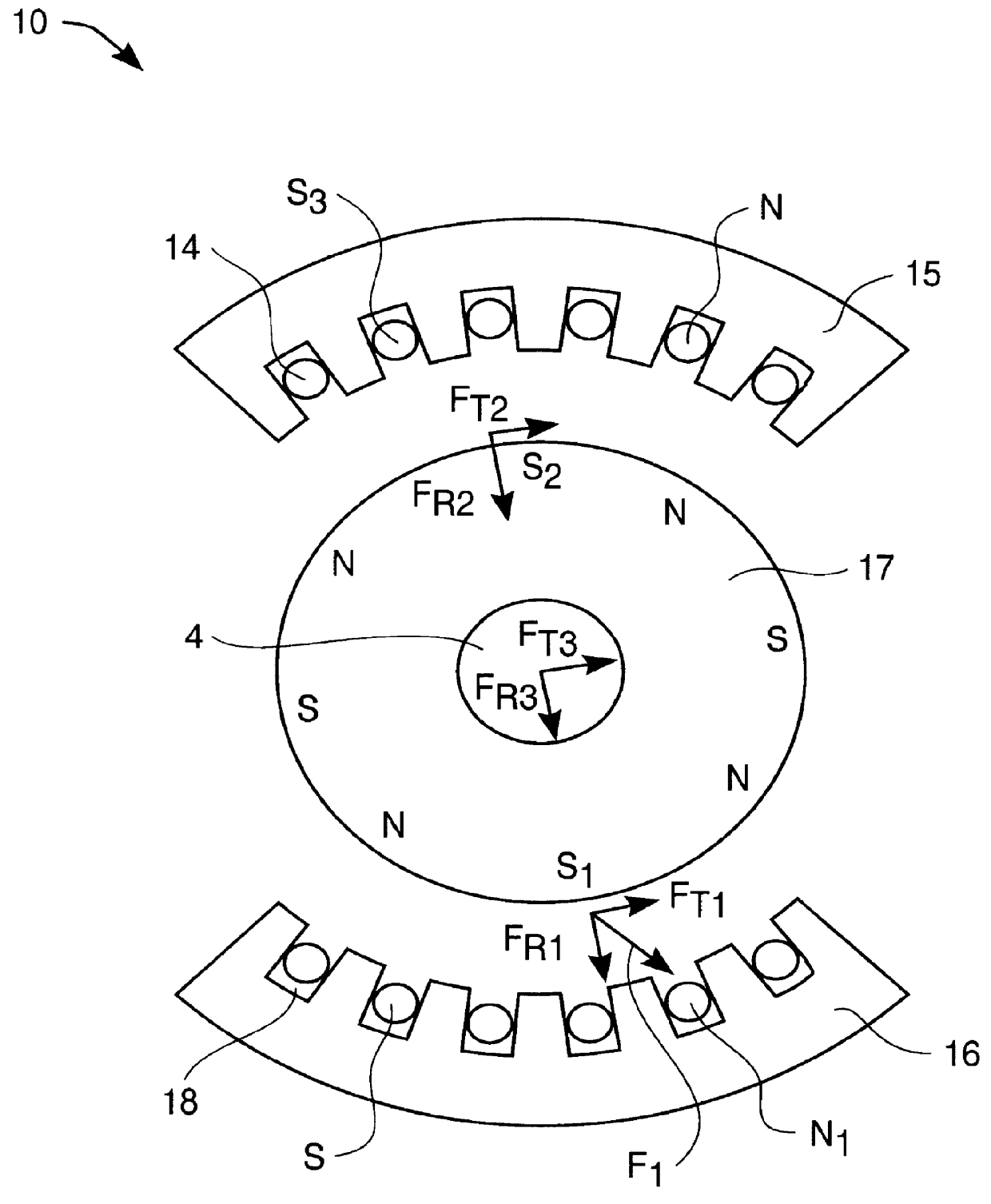
It accomplishes this purpose through a system for active reduction of radial vibrations of a shaft, especially the drive shaft of an internal combustion engine with at least one active electromagnetic device, which is designed and controlled such that it applies radial forces to the shaft, which counteract the radial vibrations of the shaft.

Radial vibrations are excited by virtue of the periodically occurring gas and mass forces with a frequency corresponding to the rotary speed of the motor or a multiple thereof. In addition, there are irregular (sometimes stochastic) excitations of radial vibrations which may result, for example, from backfiring.

The active reduction of radial vibrations occurs, in particular, such that the force applied by the active electromagnetic device is each time directed opposite the instant...


PUM


Abstract

PCT No. PCT / DE96 / 01665 Sec. 371 Date Jul. 23, 1998 Sec. 102(e) Date Jul. 23, 1998 PCT Filed Aug. 31, 1996 PCT Pub. No. WO97 / 08477 PCT Pub. Date Mar. 6, 1997The invention concerns a system for active reduction of radial vibrations of a rotating shaft (4), especially the drive shaft of an internal combustion engine (1), with at least one active electromagnetic device (7; 10; 15, 16), which is configured and controlled such that it applies radial forces to the shaft (4), which counteract the radial vibrations of the shaft (4).

Description

1. Field of the InventionThe present invention relates to systems for reducion of radial vibrations of a rotating shaft.2. Description of the Related ArtThe invention concerns a system for active reduction of radial vibrations of a rotating shaft.In piston engines, a multitude of various vibrations occurs as a result of the masses moving back and forth, as well as of the discontinuous combustion in the chamber. Besides vibrations of the overall engine, the drive shaft (i.e., the crankshaft) is excited in radial vibrations relative to the engine housing containing it. Because of the practically no-play mounting of the crankshaft in the radial direction, these vibrations are bending vibrations. Excitation of the vibrations occurs primarily through the radial components of the mass forces on the crank pins.The bending vibrations represent a high stress on the crankshaft. Therefore, the crankshaft must be correspondingly heavily dimensioned in terms of strength. This requires, in partic...

Claims


Application Information

Patent Timeline
Patent Type & Authority Patents(United States)
IPC IPC(8): B60L11/12B60K6/04B60K6/00B60L7/28B60K6/06B60L11/02B60L7/00B60T1/00B60T1/10B60K28/16F02B75/06F02B75/00F16F15/18F16F15/10F02B67/04F16F15/12F16F15/129H02K7/10H02K51/00H02K7/108F16H61/04B60K6/26B60K6/387F02N11/04B60K6/44B60K26/00B60L50/15B60L50/16B60W10/06B60W10/08B60W10/18B60W20/00F02D29/02F16C39/06F16F15/03G05D19/02H02K33/16
CPCB60K6/26B60K6/44B60K28/16B60L7/003B60L7/28B60L11/12B60T1/10B60W10/08B60W30/20F02B67/04F02B75/06F16F15/1292F16F15/18H02K7/108H02K51/00B60K6/387Y10T477/26B60K2001/003B60K2006/262B60L2220/52B60L2240/443B60W20/00B60W2510/0657F02D2250/24F02N11/0866F16H2061/0422Y02T10/623Y02T10/641Y02T10/7077Y10S903/903Y10S903/946Y10S903/906Y10S903/914Y10S903/947Y10S903/96B60L2200/26B60L2270/145Y02T10/62Y02T10/64B60K2006/268F02N11/04B60W10/26B60K6/22B60W20/10
Inventor MASBERG, ULLRICHPELS, THOMASZEYEN, KLAUS-PETERGRUNDL, ANDREASHOFFMANN, BERNHARD
Owner CONTINENTAL ISAD ELECTRONICS SYST GMBH & CO KG
Why Eureka
Try Eureka