
Omnidirectional ultra-wideband monopole antenna

a monopole antenna, ultra-wideband technology, applied in the direction of antennas, antennas with plural divergent straight elements, elongated active elements, etc., can solve the problems of poor radiation stability and omnidirectional property, difficult to meet practical needs, and difficult to obtain good yield, etc., to achieve good omnidirectional radiation patterns, simple structure, and enhanced impedance matching

Active Publication Date: 2006-04-06
IND TECH RES INST
View PDF15 Cites 20 Cited by
  • Summary
  • Abstract
  • Description
  • Claims
  • Application Information

AI Technical Summary

Benefits of technology

[0013] Aside from adjusting the length ratio of two adjacent side edges of the first sub-radiating member to tune the input impedance of the antenna, the invention further adjusts the distance between the first sub-radiating member and the ground plane to achieve an enhanced impedance matching for frequencies across the desired ultra-wideband operation.
[0014] Using this antenna structure can control the gain variation of the azimuthal radiation pattern less than 3 dB for all frequencies across a very wide operating bandwidth. That is, the invention can provide good omnidirectional radiation patterns.
[0015] The disclosed omnidirectional ultra-wideband monopole antenna has the characteristics of simple structure, easy fabrication, high yield, and low cost.

Problems solved by technology

Although this type of antennas can provide an ultra-wide operating bandwidth, their radiation stability and omnidirectional property become worse as the operating frequency increases.
Therefore, they cannot satisfy practical needs.
However, the drawback of this structure is its complicated structure, which makes good yield difficult to obtain.
Although such a structure can generate many different resonant frequencies, its drawback is also its complicated structure and high production cost.
The whole antenna is too large in size.
The antenna structure disclosed in the U.S. Pat. No. 5,828,340 cannot satisfy the requirement of omnidirectional radiation patterns and provide a sufficiently wide operating bandwidth.

Method used


Image

  • Omnidirectional ultra-wideband monopole antenna
  • Omnidirectional ultra-wideband monopole antenna
  • Omnidirectional ultra-wideband monopole antenna

Examples


Embodiment Construction

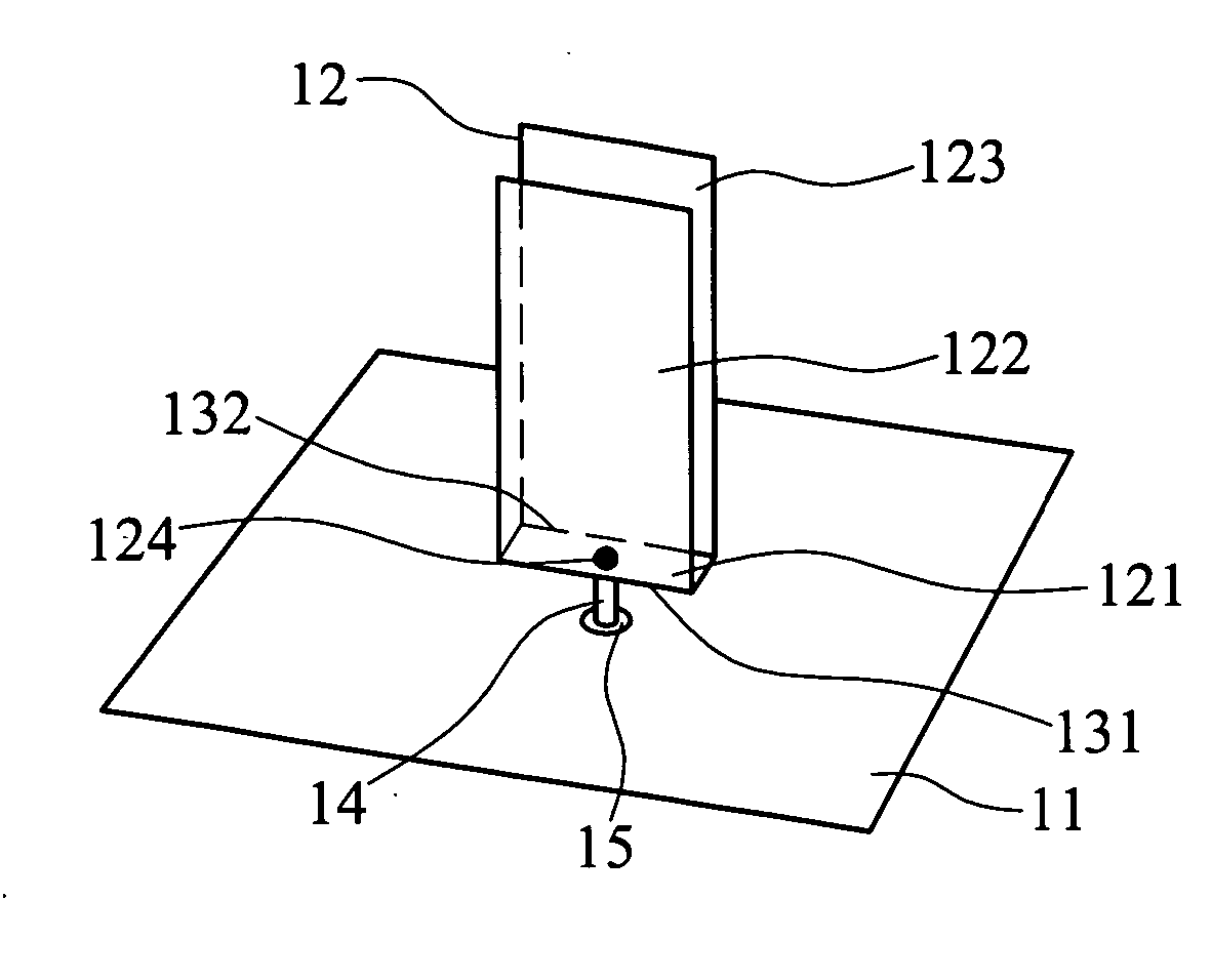
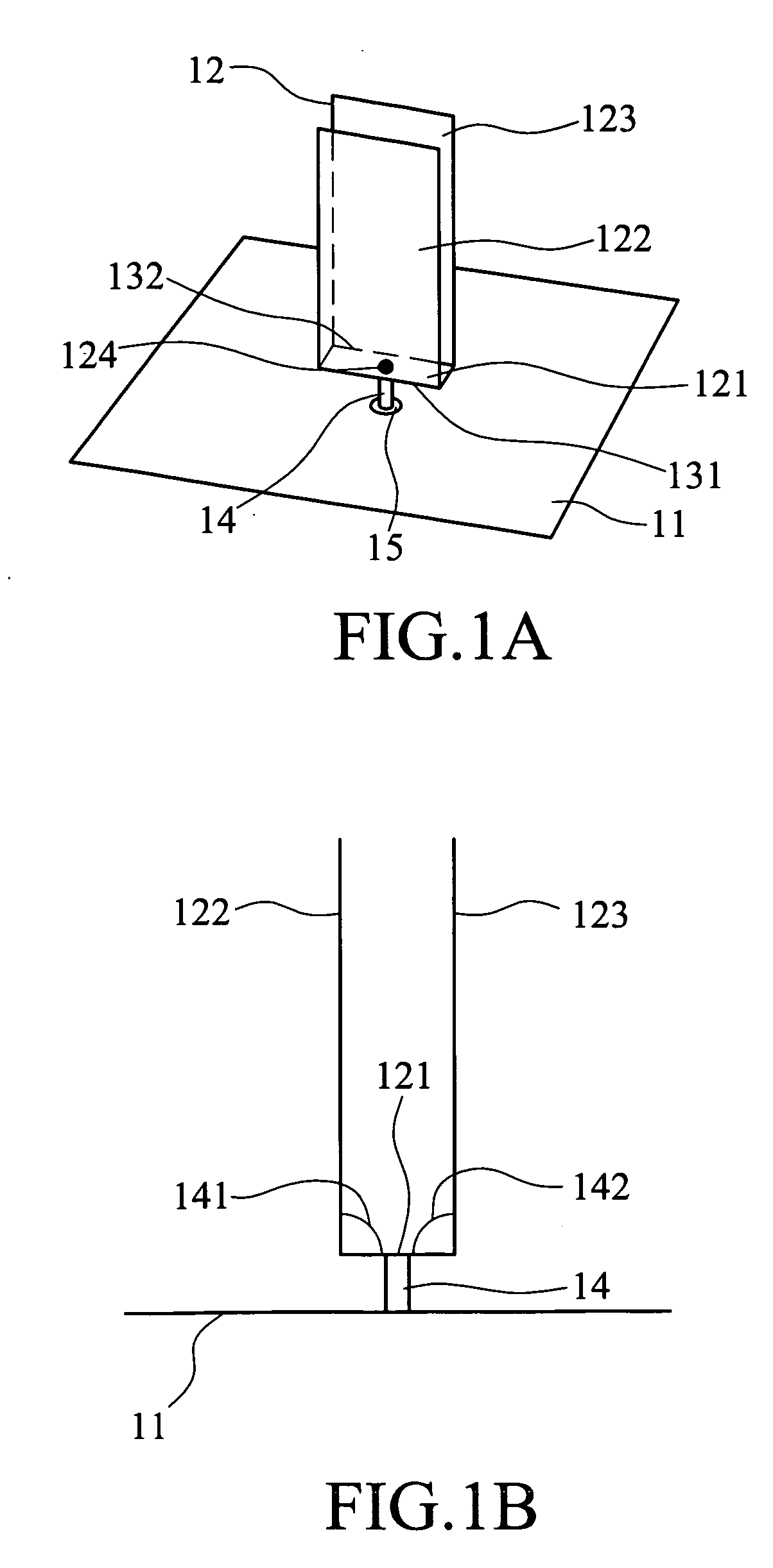
[0028] The disclosed omnidirectional ultra-wideband monopole antenna, as shown in FIGS. 1A and 1B, mainly includes: a ground plane 11, a radiating member 12, and a feeding member 14.

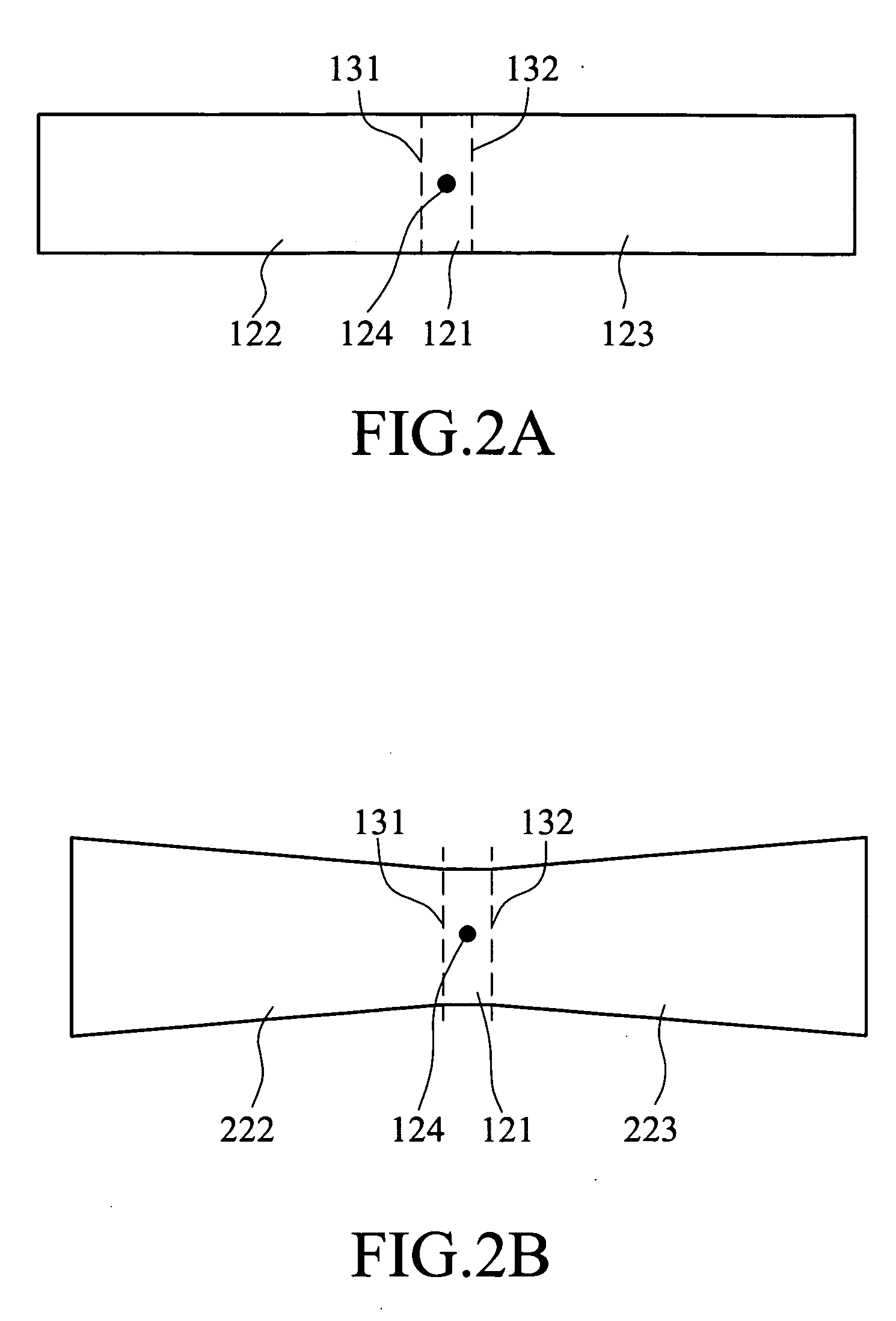
[0029] The radiating member 12 is U-shaped and installed above the ground plane 11. It includes a first sub-radiating member 121 parallel to the ground plane 11, with a first side edge 131 and a corresponding second side edge 132, a second sub-radiating member 122 connected to the first side edge 131 and perpendicular to the first sub-radiating member 121, forming a first angle 141 between them, and a third sub-radiating member 123 connected to the second side edge 132 and perpendicular to the first sub-radiating member 121, forming a second angle 142 between them. The second sub-radiating member 122 and the third sub-radiating member 123 are extended in the same upright direction above the ground plane.

[0030] The feeding member 14 receives signals from an external signal source (not shown) through ele...


PUM


Abstract

An omnidirectional ultra-wideband monopole antenna, with the characteristics of simple structure, easy fabrication and low cost, mainly comprises a ground plane, a U-shaped radiating member above the ground plane and a feeding member for feeding signals to the radiating member. The radiating member further comprises a first sub-radiating member parallel to the ground plane, with a first side edge and a corresponding second side edge, a second sub-radiating member connected to the first side edge and perpendicular to the first sub-radiating member, forming a first angle therebetween, and a third sub-radiating member connected to the second side edge to form a second angle. The second sub-radiating member and the third sub-radiating member are extended in the same upright direction above the ground plane. The antenna can provide good omnidirectional radiation patterns for frequencies across a very wide operating bandwidth.

Description

BACKGROUND OF THE INVENTION [0001] 1. Field of Invention [0002] The invention relates to an ultra-wideband monopole antenna structure and, in particular, to an omnidirectional ultra-wideband monopole antenna that provides good omnidirectional radiation patterns for frequencies across a very wide operating bandwidth. [0003] 2. Related Art [0004] With the continuous development and advance of digital audio / video (AV) and mobile communications in wireless local area network (WLAN), there have been demands for higher data transmission rate. [0005] The IEEE 802.15 WPAN (Wireless Personal Area Network) put forward by the Institute of Electrical and Electronics Engineers is a standard for ultra-wideband operation with a high data transmission rate. For practical design considerations of the antennas for such an ultra-wideband operation, in addition to providing a wide operating bandwidth with a frequency ratio over 1:3, the antenna has to maintain stable omnidirectional radiation patterns ...

Claims


Application Information

Patent Timeline
IPC IPC(8): H01Q21/00
CPCH01Q9/40H01Q9/42H01Q9/44
Inventor TANG, CHIA-LUNYEH, SHIH-HUNGWONG, KIN-LUSU, SAOU-WENWU, CHIH-HSIEN
Owner IND TECH RES INST
Learn More