Coupled-fed multi-band loop antenna

a multi-band loop antenna and coupled-fed technology, applied in the direction of resonant antennas, substantially flat resonant elements, radiating element structural forms, etc., can solve the problem of difficult reduction of antenna size, and achieve good impedance matching, simple structure, and good impedance matching

Active Publication Date: 2011-07-12
ACER INC
View PDF12 Cites 48 Cited by
  • Summary
  • Abstract
  • Description
  • Claims
  • Application Information

AI Technical Summary

Benefits of technology

[0005]Therefore, one of the objectives of the present invention is to provide a loop antenna for the mobile phone, capable of covering GSM (890˜960 MHz) / DCS (1710˜1880 MHz) / PCS (1850˜1990 MHz) / UMTS (1920˜2170 MHz) operations for the mobile phone, and the size of the antenna of the present invention is only half of the conventional mobile phone antenna operating at the same frequency band. Besides, such an antenna has the advantages of simple structure, clear operating mechanism, easy fabrication, and saving of the inner space of the mobile phone.
[0014]In the antenna of the present invention, the coupling feed is used to excite the ¼-wavelength resonant mode of the radiating loop-shaped metal strip, so that a lower band with good impedance matching can be formed. The ½-wavelength and one-wavelength resonant modes of the radiating loop-shaped metal strip are combined to form a wide operating band, and the matching component group is used to compensate for the large imaginary part of these two modes, and thereby an upper band with good impedance matching can be formed. The lower band, which is ¼-wavelength resonant mode, provides an operating bandwidth of about 100 MHz (890˜990 MHz), which covers GSM operation. The return loss of this antenna in this required band is better than 6 dB. The upper band, which is formed by the ½-wavelength and one-wavelength resonant modes, provides an operating bandwidth of 500 MHz (1700˜2200 MHz), which can cover DCS / PCS / UMTS operation. The return loss in this required band ranging from 1710˜2170 MHz is better than 6 dB, and this can satisfy the communication application requirement. Meanwhile, the antenna of the present invention not only has a simple structure and a clear operating mechanism, but also shows a significantly reduced size when compared with the conventional mobile phone antenna operating at the same frequency band. This means the antenna of the present invention requires a much smaller volume inside the mobile phone. Therefore, the present invention has value of industrial application.

Problems solved by technology

The half-wavelength mode is provided for GSM operation, which makes the antenna size difficult to be reduced.

Method used


Image

  • Coupled-fed multi-band loop antenna
  • Coupled-fed multi-band loop antenna
  • Coupled-fed multi-band loop antenna

Examples


Embodiment Construction

[0026]Exemplary embodiments of the present invention are described herein in the context of a coupled-fed multi-band loop antenna.

[0027]Those of ordinary skilled in the art will realize that the following detailed description of the exemplary embodiment(s) is illustrative only and is not intended to be in any way limiting. Other embodiments will readily suggest themselves to such skilled persons having the benefit of this disclosure. Reference will now be made in detail to implementations of the exemplary embodiment(s) as illustrated in the accompanying drawings. The same reference indicators will be used throughout the drawings and the following detailed description to refer to the same or like parts.

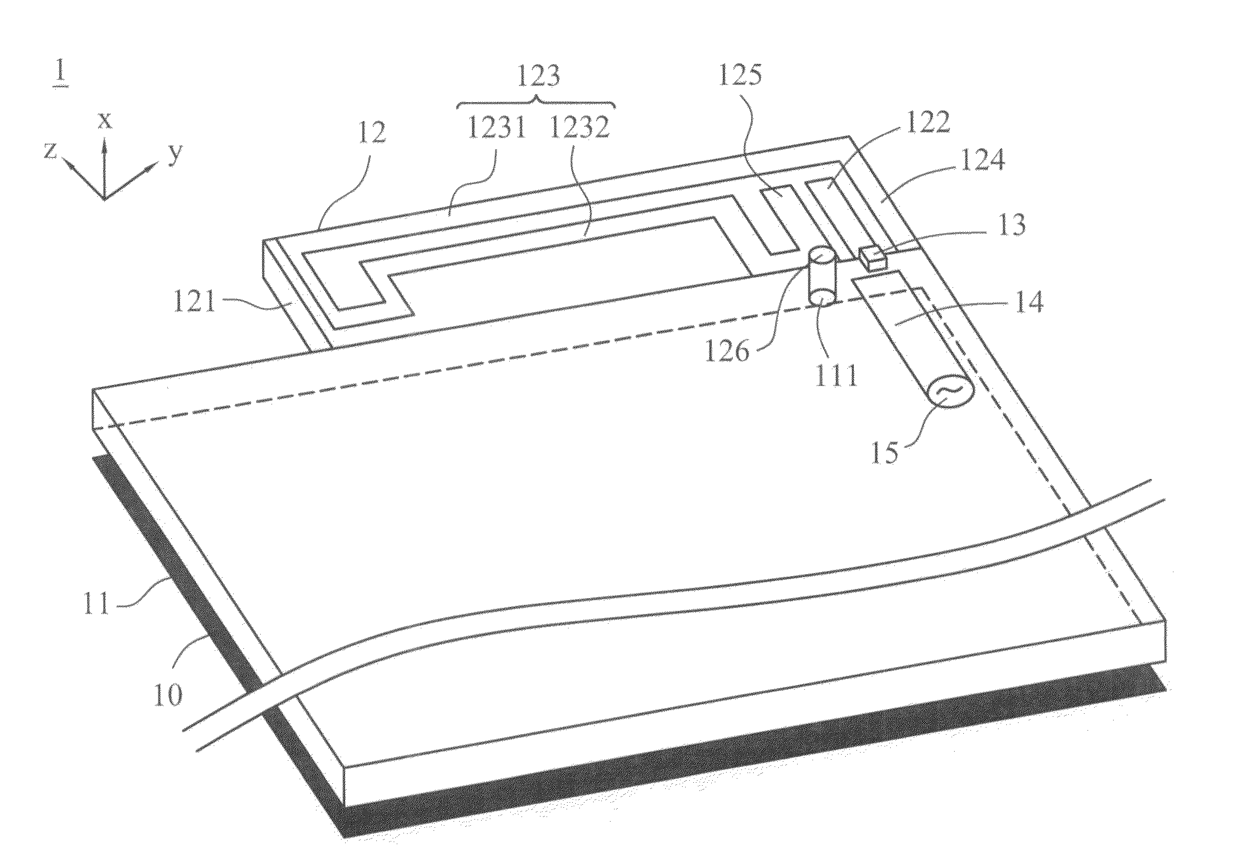
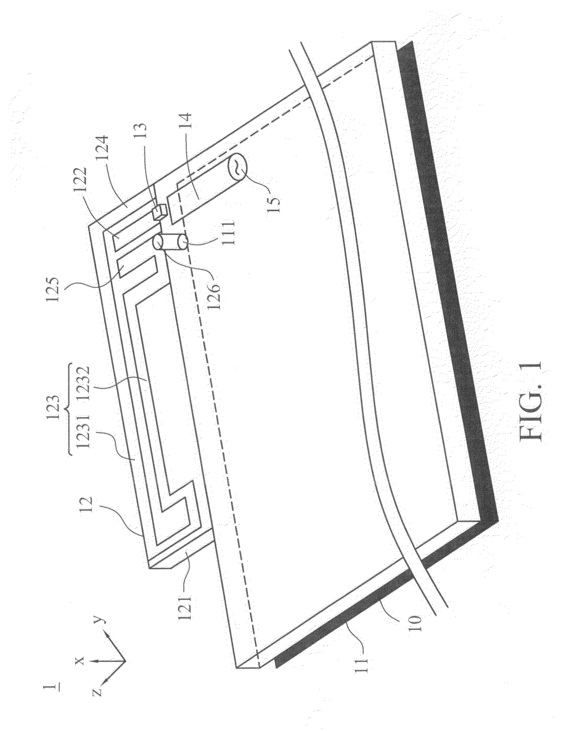
[0028]FIG. 1 illustrates a structural drawing of the first embodiment of the antenna in the present invention. Embodiment 1 comprises a dielectric substrate 10, a ground plane 11, a radiating portion 12 and a matching component group 13. The ground plane 11 is located on the dielectric...


PUM


Abstract

The present invention is related to a coupled-fed multi-band loop antenna. The antenna comprises a dielectric substrate, a ground plane located on the dielectric substrate and has a grounding point, a radiating portion which comprise a supporter, a coupling trip and a loop strip, and a matching circuit. The coupling strip and loop strip are both located on the supporter, with the coupling strip surrounded by the loop strip. The length of loop strip is about 0.25 wavelength of the antenna's first resonant mode. The loop strip has a first end paralleling with the coupling loop, a second end and a shorting point near the second end and electrically connected to the grounding point on the ground plane. The matching circuit is on the dielectric substrate. One terminal of the matching circuit is connected to the coupling strip, and the other is connected to a signal source.

Description

RELATED APPLICATIONS[0001]This application claims a priority under 35 U.S.C. 119 to Application TAWAIN 097116537, filed on May 5, 2008, the disclosures of which Applications are incorporated by reference herein.FIELD OF THE INVENTION[0002]The present invention is related to a loop antenna, particularly to a coupled-fed multi-band loop antenna which is suitable to be installed in mobile communication devices.BACKGROUND OF THE INVENTION[0003]With the rapid development of wireless communication, all wireless communication products are made light, thin, short and small in appearance in trend and in fashion so as to cater to the demand of consumers market. Meanwhile, the wireless communication product is required to provide various services; it means that more and more system modules and elements will be installed in the limited space of the wireless communication product. Hence, the space for installing the antenna will be compressed significantly.[0004]Because the conventional monopole...

Claims


Application Information

Patent Timeline
Patent Type & Authority Patents(United States)
IPC IPC(8): H01Q11/12H01Q1/38H01Q5/357
CPCH01Q1/243H01Q7/00H01Q5/357H01Q9/0421H01Q9/0457H01Q9/0407
Inventor CHI, YUN-WENWONG, KIN-LU
Owner ACER INC
Why Eureka
Try Eureka