Radio frequency identification tag having an inductively coupled antenna

a radio frequency identification and inductively coupled technology, applied in the field of radio frequency identification tags, can solve the problems of limiting the ability to make cheaper and smaller rfid tags, adding to the cost of rfid tags, and conductive electrical connections, so as to improve reliability, reduce assembly costs, and increase flexibility

Inactive Publication Date: 2006-01-19
SARNOFF CORP
View PDF11 Cites 45 Cited by
  • Summary
  • Abstract
  • Description
  • Claims
  • Application Information

AI Technical Summary

Benefits of technology

[0006] An RFID tag according to the principles of the invention couples a radiating element or antenna on a substrate to an RFID tag integrated circuit without a physical conductor. The radiating element or antenna comprises a coil, also referred to as the antenna coil. Likewise, the integrated circuit has electronic circuitry connected to a coil also called the circuit chip coil. The integrated circuit is affixed to the substrate having the antenna in such a way that the circuit chip coil is inductively coupled to the antenna coil. When the RFID tag is excited via the antenna, the inductive coupling causes both signaling and power to couple from the antenna coil to the circuit chip coil without a physical conductor connecting the antenna to the RFID tag integrated circuit. Without limitation, the advantages of an RFID tag according to the principles of the invention can be significantly lower assembly costs, higher reliability, increased flexibility and ease of impedance matching between the integrated circuit and the antenna.

Problems solved by technology

The limitation of all such known methods for coupling an RFID chip to an antenna is that such connections involve a conductive electrical connection.
Such connections limit the ability to make cheaper and smaller RFID tags such that can be used in the most inexpensive applications.
Further, the use of conductive connections requires that a portion of the chip have open passivation, further adding to the costs of the RFID tag.
Moreover, conventional technique of using bonding pads does not work well in a semi-rigid or flexible structure such as a label or paper.

Method used


Image

  • Radio frequency identification tag having an inductively coupled antenna
  • Radio frequency identification tag having an inductively coupled antenna
  • Radio frequency identification tag having an inductively coupled antenna

Examples


Embodiment Construction

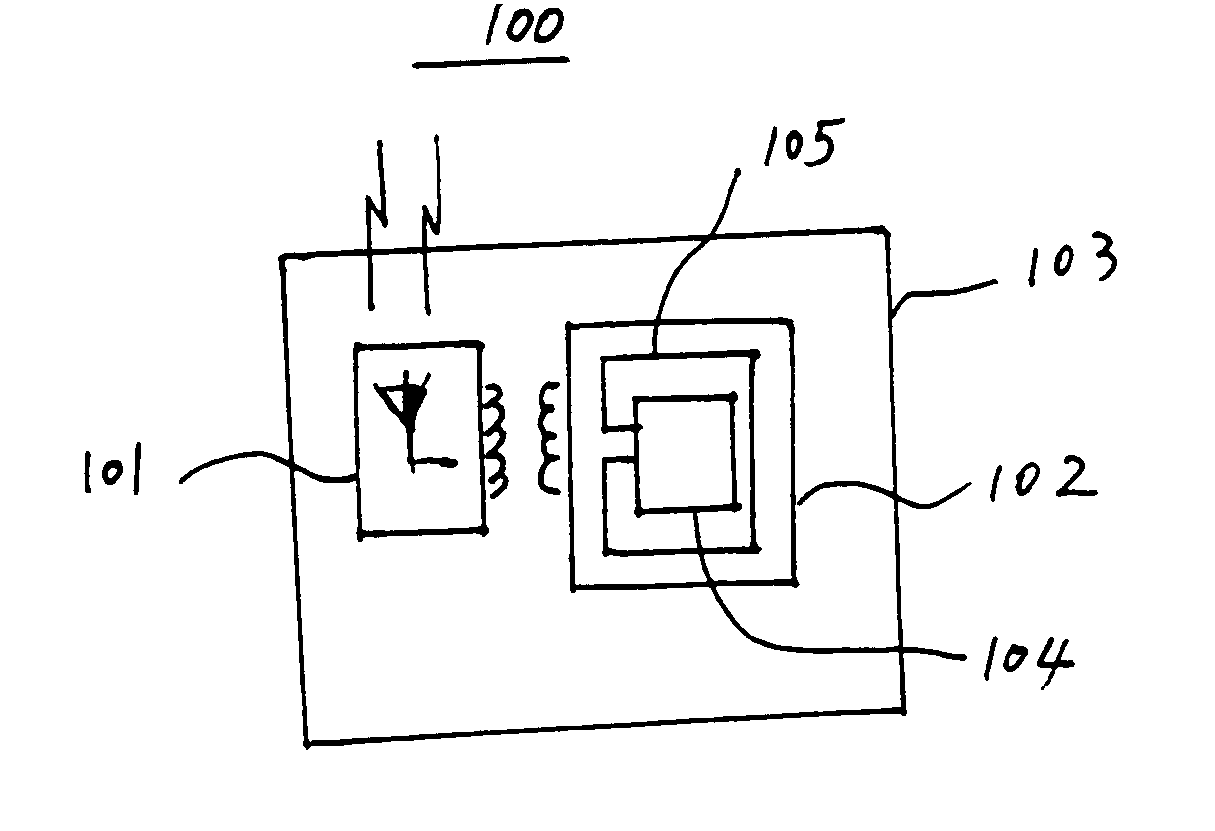
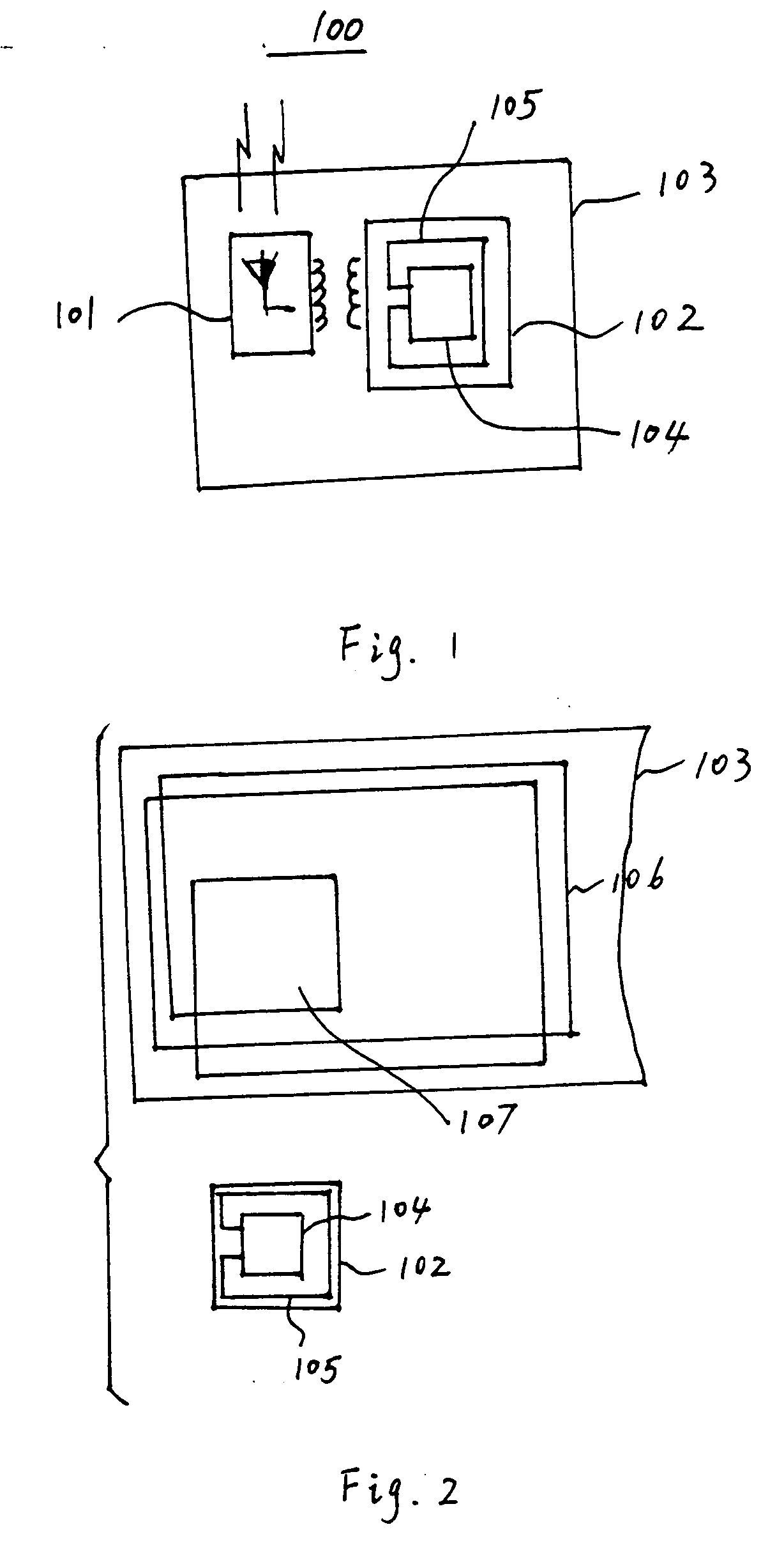
[0012] Referring to FIG. 1, an RFID tag 100 according to the principles of the invention includes a radiating element or antenna 101 and an integrated circuit chip 102. The antenna 101 and chip 102 are placed within or upon a carrier or support 103. The carrier 103 can be a rigid substrate, or a semi-rigid or flexible material such as a sheet of paper or plastic. The radiating element 101 can communicate with both an outside antenna (not shown) and the integrated circuit 102 inside the RFID tag 100. The integrated circuit 102 comprises an electronic circuitry 104 and a coil 105 which is also called an integrated circuit coil. The integrated circuit 102 provides the primary identification functions. It can, for example, store the tag identification and other desirable information, interpret and process commands received from the interrogation hardware and respond to requests for information by the interrogator. Within the RFID tag 100, the radiating element 101 is inductively coupled...


PUM


Abstract

An RFID tag which couples a radiating element or antenna to an integrated circuit without a physical conductor. The radiating element comprises a coil. The integrated circuit is affixed to the substrate having the antenna in such a way that the circuit chip coil is inductively coupled to the antenna coil. When the RFID tag is excited via the antenna, the inductive coupling causes both signaling and power to couple from the antenna to the circuit chip coil without a physical conductor connecting the antenna to the RFID tag integrated circuit.

Description

FIELD OF THE INVENTION [0001] The present invention relates to the field of radio-frequency identification (RFID) tags including, but not limited to, RFID tags having an inductively coupled antenna. BACKGROUND OF THE INVENTION [0002] RFID tags and radio frequency identification tag systems are known, and find numerous uses. For example, RFID tags are frequently used for personal identification in automated gate sentry applications to protect and secure buildings or areas. Information stored on the RFID tag identifies the person seeking access to the building. An RFID tag system conveniently provides for reading the information from the RFID tag at a small distance using radio frequency data transmission technology. Typically, the user simply holds or places the radio frequency identification tag near a base station that transmits an excitation signal and communicates the stored information from the RFID tag through the base station, which receives and decodes the information. In gen...

Claims


Application Information

Patent Timeline
Patent Type & Authority Applications(United States)
IPC IPC(8): G08B13/14
CPCG06K19/0723G06K19/07749G06K19/07756
Inventor ZALUD, PETERSCHEPPS, JON
Owner SARNOFF CORP
Why Eureka
Try Eureka