Controlled motion system

a technology of motion system and control panel, which is applied in the direction of propulsion system, motor/generator/converter stopper, dynamo-electric converter control, etc., can solve the problems of inability to maintain the positive control of the mover, the production is lost, and the nonlinear section is one limitation, so as to reduce assembly costs

Active Publication Date: 2010-12-28
ROCKWELL AUTOMATION
View PDF10 Cites 38 Cited by
  • Summary
  • Abstract
  • Description
  • Claims
  • Application Information

AI Technical Summary

Benefits of technology

[0008]In another preferred embodiment soft magnetic composite materials are used for the motor core of the controlled motion system. This advantageously allows nonlinear shaped smart sections with complex core geometries to be utilized without the large core losses of prior art systems. Also, soft magnetic composite cores allow the windings to be directly wound onto the core pole pieces and then assembled into the motor core, reducing assembly costs.

Problems solved by technology

One limitation is on nonlinear sections.
A key problem with this prior art system is that in the transition zone from the “smart” to the “dumb” sections positive control of the mover is not maintained.
This means it is possible for a mover to get stuck with no means of recovery other than operator intervention, which causes down time and lost production.
This design suffers from large eddy currents leading to braking and loss of efficiency.
A key problem with these prior art single-sided movers is that they are not fully constrained against applied loads in any direction.

Method used


Image

  • Controlled motion system
  • Controlled motion system
  • Controlled motion system

Examples


Embodiment Construction

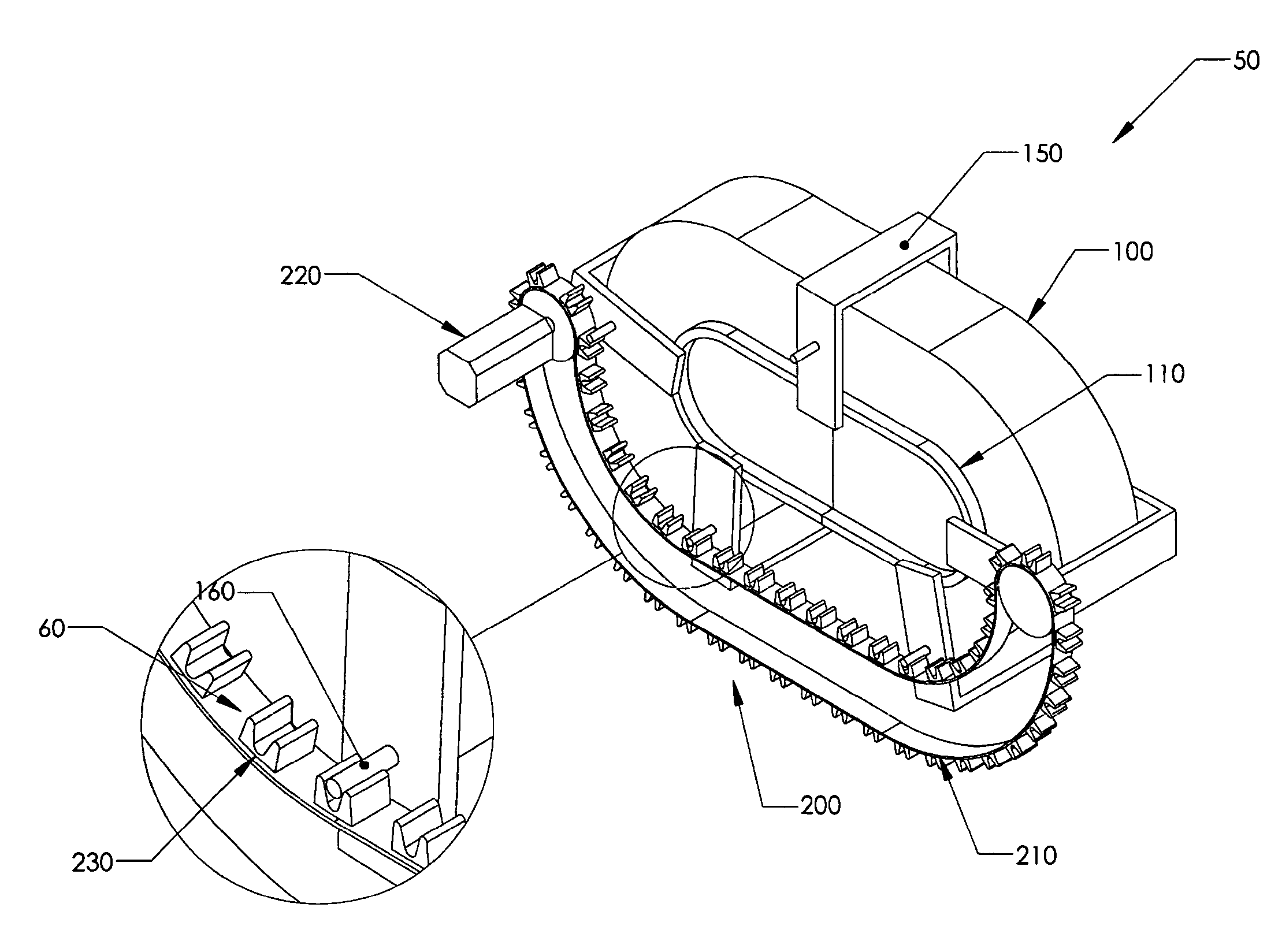
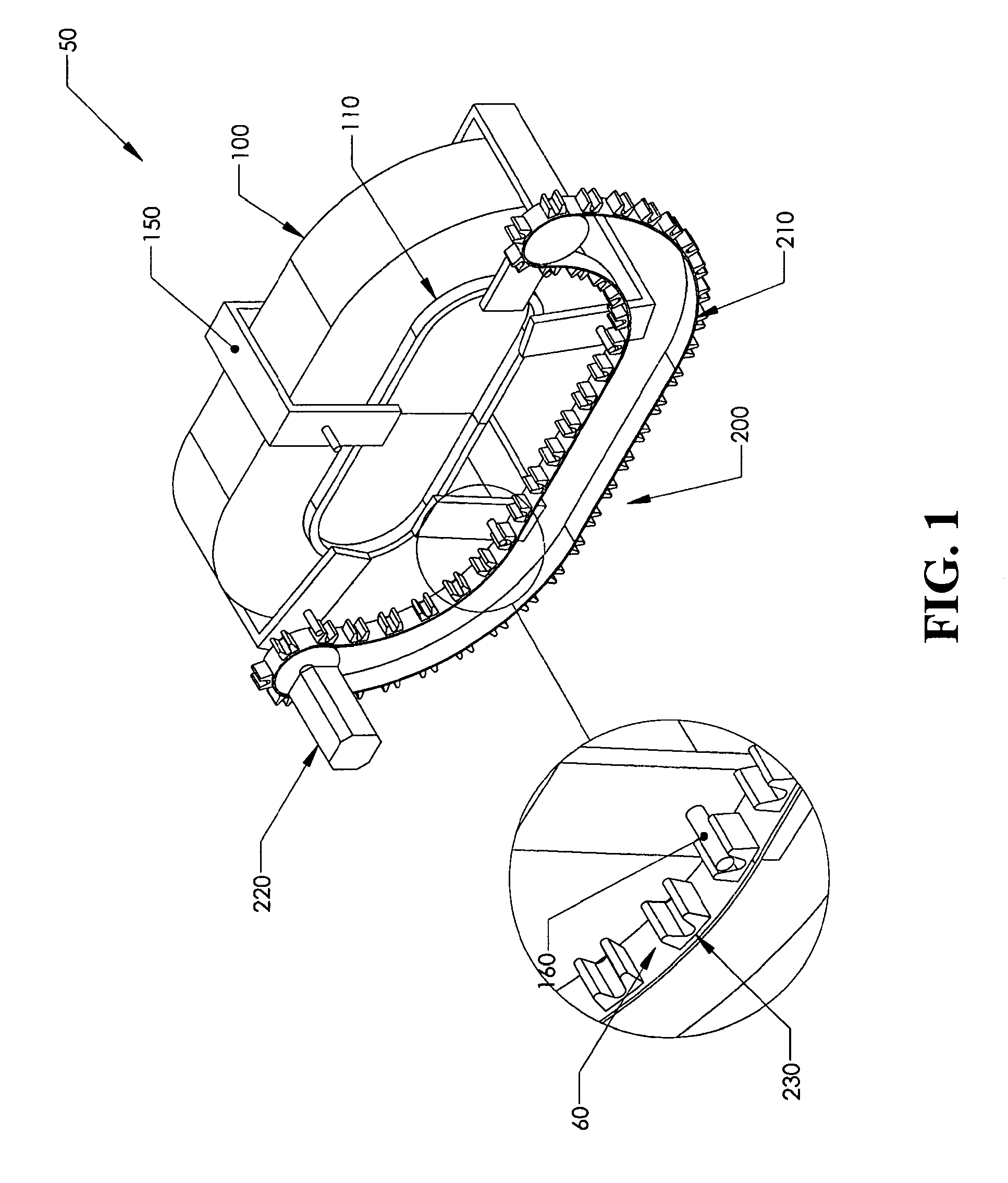
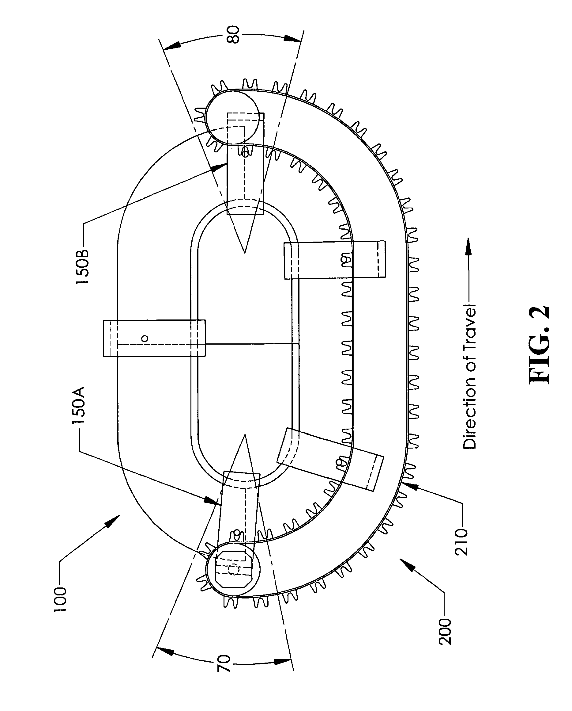
[0018]FIG. 1 illustrates a preferred embodiment of a hybrid track system 50, comprised of at least one “smart” section 100 and at least one “dumb” section 200. Movers 150 are movably mounted on bearing system 110 such that the movers are constrained to transverse a path defined by this bearing system 110. A “smart” section 100 is characterized by its ability to independently control each of the movers 150 that is in its realm of control. This type of motor section is disclosed in U.S. Pat. No. 6,876,107. In contrast, a “dumb” section 200 lacks the ability to independently control each of the movers 150 and drives all of the movers 150 in its realm of control at the same speed.

[0019]In a preferred embodiment, dumb section 200 comprises a belt or chain 210 driven by a rotary motor 220. The belt or chain 210 has at least one driving feature 230 that couples to a driven feature 160 on the movers 150 so that movers 150 can be driven along the dumb section 200. In the illustrated embodime...


PUM


Abstract

A controlled motion system with movers mounted on a hybrid track system comprised of at least one smart section and at least one dumb section. The smart sections control each mover independently, while the dumb sections drive all movers at the same speed. The transition between these sections is characterized by positive control of the movers at all points in the transition. A soft magnetic composite core for the smart sections is disclosed. Also, a single-sided mover for smart sections that is constrained against loads in all direction, except for the direction of motion, is disclosed.

Description

CROSS-REFERENCE TO RELATED APPLICATIONS[0001]This application claims the benefit of U.S. Provisional Application No. 60 / 951,282 filed Jul. 23, 2007, the content of which is expressly incorporated herein by reference thereto.BACKGROUND OF INVENTION[0002]The present invention relates to controlled motion systems. Some aspects of the invention relate more specifically to controlled motion systems capable of independently controlling multiple movers on a track. The invention can be applied to controlled motion systems of the type disclosed in U.S. Pat. No. 6,876,107 issued Apr. 5, 2005 to Jacobs or U.S. Pat. No. 6,191,507 issued Feb. 20, 2001 to Peltier et al., both of which are incorporated herein fully by reference.[0003]These prior art systems have several limitations that the present invention overcomes. One limitation is on nonlinear sections. On one type of prior art system, linear and nonlinear shaped sections are employed to create a path over which movers travel. This type of s...

Claims


Application Information

Patent Timeline
Patent Type & Authority Patents(United States)
IPC IPC(8): H02K41/02
CPCH02K41/025H02K2201/18
Inventor JACOBS, KEITH G.
Owner ROCKWELL AUTOMATION
Why Eureka
Try Eureka