Thrust bearing assembly

a technology of thrust bearings and bearings, which is applied in the direction of shaft assemblies, sliding contact bearings, mechanical equipment, etc., can solve the problems of thrust bearing premature failure, reduce manufacturing costs, and increase manufacturing costs

Inactive Publication Date: 2006-11-14
FEDERAL MOGUL WORLD WIDE LLC
View PDF8 Cites 40 Cited by
  • Summary
  • Abstract
  • Description
  • Claims
  • Application Information

AI Technical Summary

Benefits of technology

[0010]This invention has the advantage of reduced manufacturing costs as it relates to the engine assembly. Typically, the prior art engine assemblies relied on a thrust bearing as both the upper and the lower portions. The thrust bearings are more expensive to manufacture because once the material is cut, it must be formed by bending or roll forming the flanges. This extra time and labor increases the costs of manufacturing such an assembly. Therefore, the subject invention reduces the costs by replacing one of the thrust bearings with the main bearing and the thrust washer. The thrust washers are cut or punched out from the material and positioned adjacent the main bearing. There is no additional step of bending or roll forming the flanges required.
[0011]The invention has the further advantage of enabling the bearing assembly to be customized for the particular engine assembly. Typically, the engine assembly has a larger thrust force in one direction and a lesser thrust force in the other. Therefore, the subject invention absorbs both forces while also reducing the cost of the assembly.

Problems solved by technology

This constant force has the detrimental effect of stressing the thrust bearing of the base of the thrust flanges, which can lead to premature failure of the thrust bearing.

Method used


Image

  • Thrust bearing assembly
  • Thrust bearing assembly
  • Thrust bearing assembly

Examples


Embodiment Construction

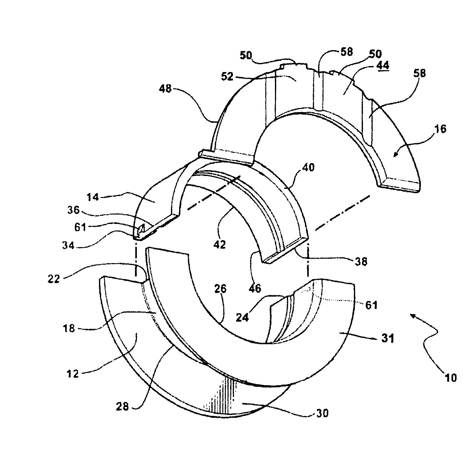
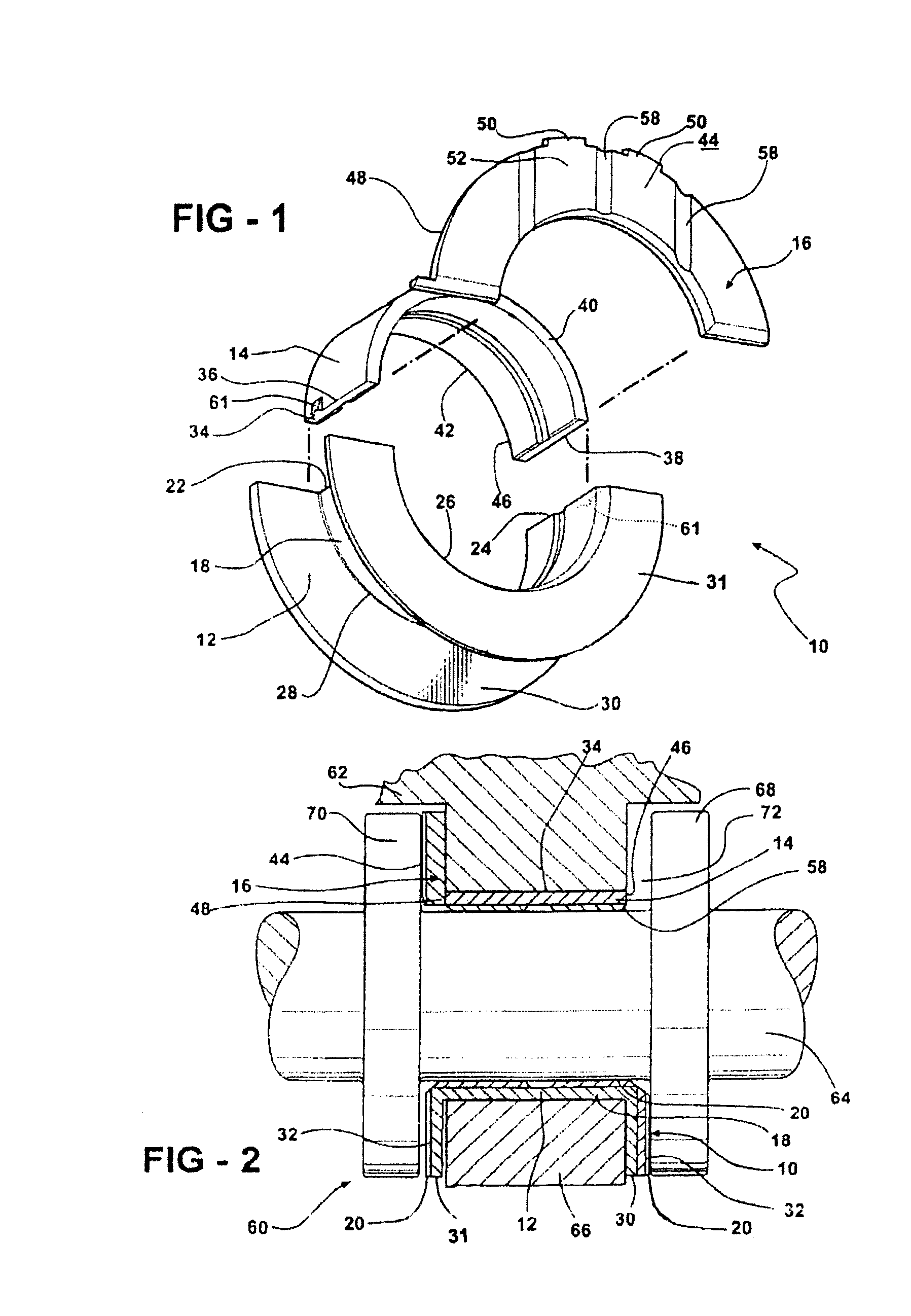
[0020]One embodiment of a thrust bearing assembly is shown generally at 10 in FIG. 1. A cross-sectional view of the thrust bearing assembly 10 is illustrated in FIG. 2. The embodiment illustrated in FIG. 1 includes a thrust bearing 12 shown as a lower portion and a main bearing 14 and a thrust flange 16 in abutting engagement thereof as an upper portion. It is to be appreciated that the upper and the lower portion may be reversed with the upper portion being the lower portion and vice versa.

[0021]The thrust bearing 12 includes an arcuate bearing shell 18 with a concave inner surface and a convex outer surface. The inner surface may include a bearing material 20 as will be described below. The shell 18 extends arcuately between first and second ends 22, 24 and extends axially between opposite edges 26, 28 thereof. The thrust bearing 12 has thrust flanges 30, 31 extending radially outwardly from the outer surface thereof forming thrust surfaces 32. One thrust flange 30 has hydrodynami...


PUM


Abstract

The subject invention provides a thrust bearing assembly having only three thrust flanges in total. One portion of the thrust bearing assembly comprises a main bearing having an arcuate bearing shell with a concave inner surface and a convex outer surface. A thrust washer having hydrodynamic features abuts one of the edges of the main bearing and extends radially outwardly from the outer surface thereof forming a thrust surface. The other of the edges of the main bearing is free of a flange. The free edge of the main bearing is preferably spaced inward from other thrust surfaces and the edge has a substantially narrower width than the other thrust surfaces. The other portion of the assembly may include a traditional thrust bearing having one thrust flange with hydrodynamic features and another thrust flange free of hydrodynamic features, both extending radially outwardly therefrom or may include another main bearing abutting a pair of thrust washers, one having hydrodynamic features and one free of hydrodynamic features, extending radially outwardly from the other main bearing. In either configuration, the thrust flange or thrust washer that is free of hydrodynamic features is opposite the thrust washer having hydrodynamic features of the main bearing.

Description

BACKGROUND OF THE INVENTION[0001]1. Field of the Invention[0002]The subject invention relates to a thrust bearing assembly as part of an engine assembly for use in a vehicle.[0003]2. Description of the Related Art[0004]Crankshafts are journaled in engine blocks by a series of axially spaced engine bearing assemblies. Each engine bearing assembly includes an upper portion seated in an arcuate recess of the block and an accompanying lower portion clamped tightly against the upper bearing half by a supportive bearing cap bolted to the engine block. At least one of the engine bearings in the set is designed to absorb axial thrust forces imported by the crankshaft during operation. The so-called thrust bearing differs from the other engine bearing in that it has two axially spaced thrust flanges that project radially outwardly. The thrust bearing presents opposite axially outwardly directed thrust faces which are seated on their backsides against the support surfaces of the block and eng...

Claims


Application Information

Patent Timeline
Patent Type & Authority Patents(United States)
IPC IPC(8): F16C9/02
CPCF16C9/02F16C17/10F16C33/1075F16C43/02F16C17/047F16C2226/76F16C2360/22F16C9/00F16C17/04F16C32/06F16C33/10
Inventor THOMPSON, RONALD JWELCH, SEAN MICHAEL
Owner FEDERAL MOGUL WORLD WIDE LLC
Why Eureka
Try Eureka