LED bulb

a technology of led bulbs and led filaments, applied in the field of light sources, can solve the problems of increasing installation costs, short life of bulbs, and affecting so as to reduce assembly costs, reduce the number of parts, and enhance the operation of light sources

Active Publication Date: 2006-09-19
OSRAM SYLVANIA INC
View PDF1 Cites 40 Cited by
  • Summary
  • Abstract
  • Description
  • Claims
  • Application Information

AI Technical Summary

Benefits of technology

[0008]It is another object of the invention to enhance the operation of light sources.
[0009]It is yet another object of the invention to provide a simple and yet expedient light guide system for use with light sources.
[0010]These objects are accomplished, in one aspect of the invention, by the provision of an LED light source comprising: a housing having a base; a hollow core projecting from said base, said hollow core being arrayed about a longitudinal axis; a printed circuit board positioned in said base at one end of said hollow core and having a plurality of LEDs operatively fixed thereto about the periphery thereof; a light guide with a body having a given wall thickness positioned in said hollow core and having a first end in operative relation with said plurality of LEDs and a second end projecting beyond said hollow core; a heat sink positioned in a heat-transferring relationship with said printed circuit board; and a first reflector attached to said second end of said light guide. The use of a single light guide reduces the number of parts and concomitantly reduces assembly costs. In a preferred embodiment of the invention the hollow core and the light guide are circular, thus reducing alignment concerns.

Problems solved by technology

While working well and being inexpensive, these bulbs have a relatively short life and, of course, the thin filament employed was always subject to breakage due to vibration.
However, these LED sources have been hard-wired into their appropriate location, which increases the cost of installation.
While the arrangement works well, it is expensive and requires a large number of parts, all of which require rather precise alignment.

Method used


Image

  • LED bulb
  • LED bulb
  • LED bulb

Examples


Embodiment Construction

[0017]For a better understanding of the present invention, together with other and further objects, advantages and capabilities thereof, reference is made to the following disclosure and appended claims taken in conjunction with the above-described drawings.

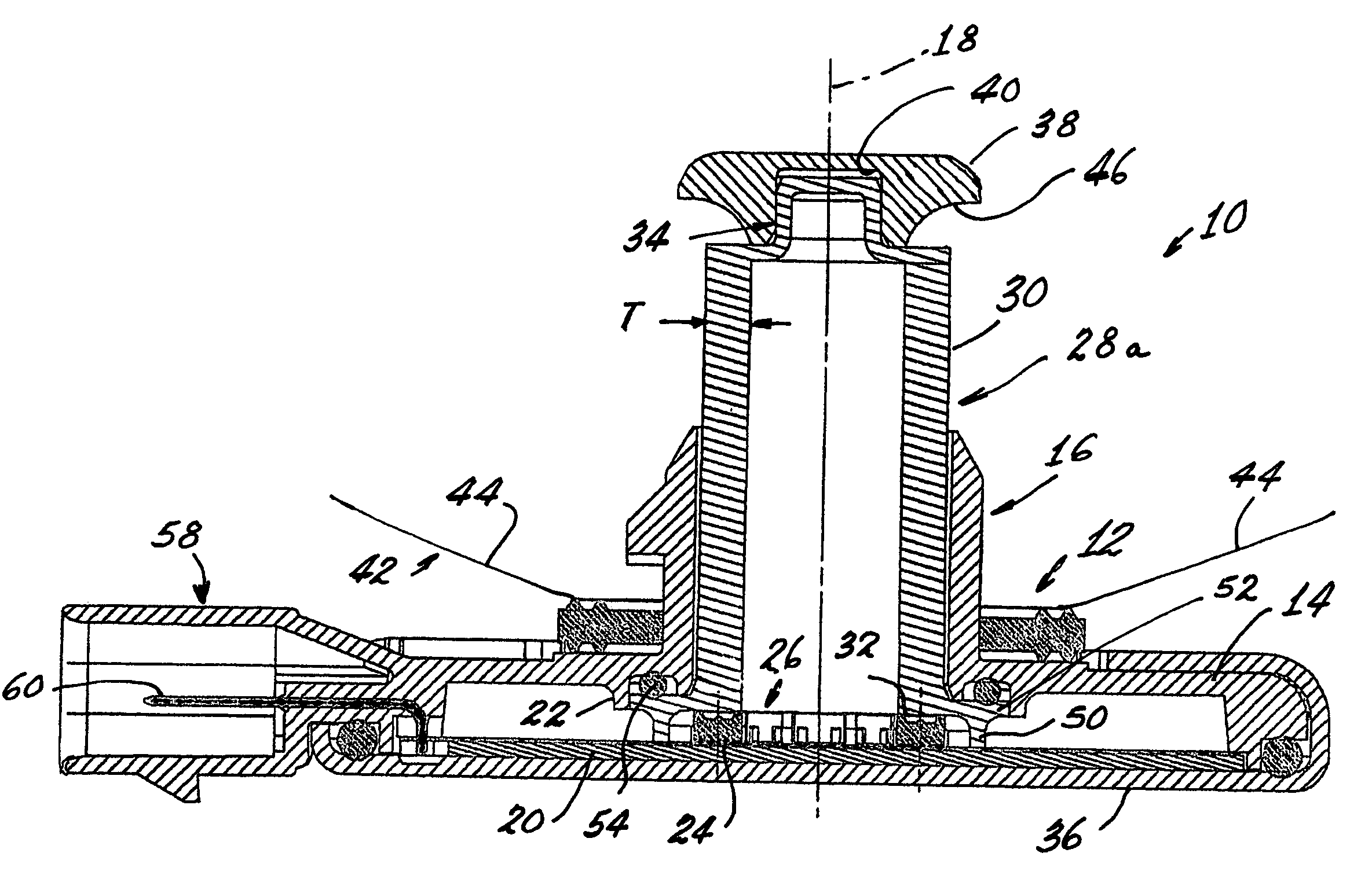
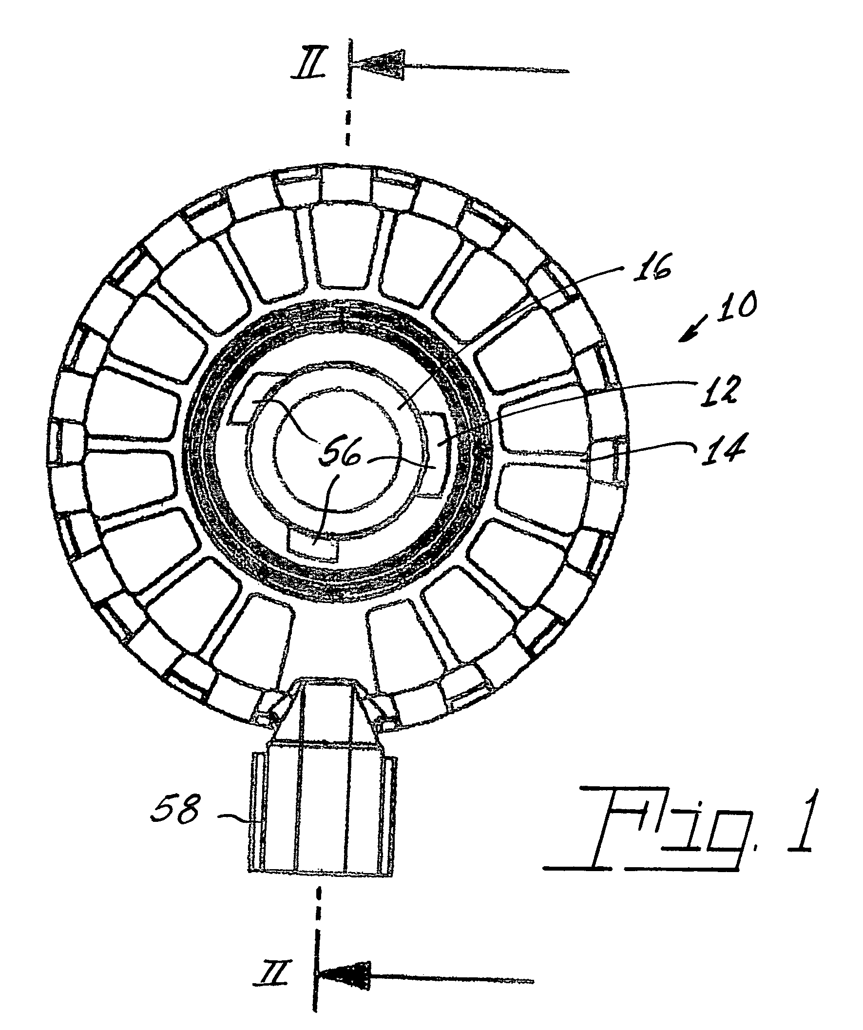
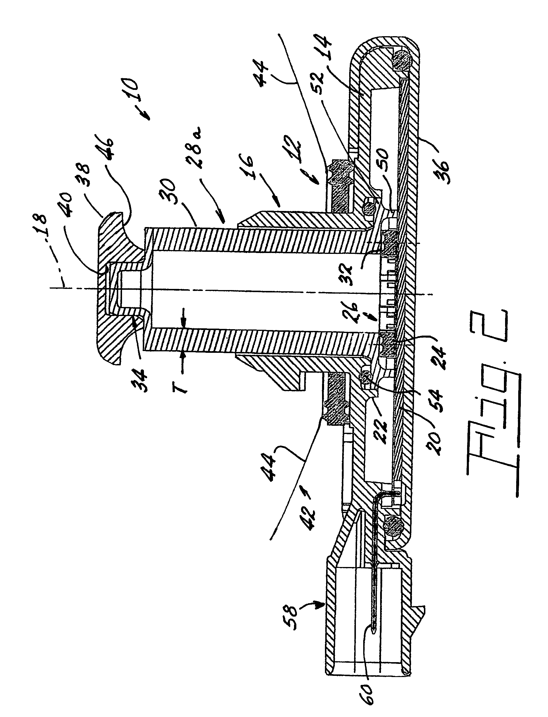
[0018]Referring now to the drawings with greater particularity, there is shown in FIGS. 1 and 2 an LED light source 10 comprising a housing 12 having a base 14. A hollow core 16 projects from the base 14 and is arrayed about a longitudinal axis 18. A printed circuit board 20 is positioned in the base 14 at one end 22 of the hollow core 16 and has a plurality of LEDs 24 operatively fixed thereto about the center thereof. In a preferred embodiment of the invention the hollow core 16 is tubular and the array of LEDs is circular. A light guide 28 with a body 30 that is, in a preferred embodiment, cup-shaped as shown in FIGS. 2 and 4a, has a given wall thickness “T”. The light guide 28 is positioned in the hollow core 16 and has a fir...


PUM


Abstract

An LED light source has a housing having a base. A hollow core projects from the base and is arrayed about a longitudinal axis. A printed circuit board is positioned in the base at one end of the hollow core and has a plurality of LEDs operatively fixed thereto about the center thereof. In a preferred embodiment of the invention the hollow core is tubular and the printed circuit board is circular. A light guide with a body that, in a preferred embodiment, is cup-shaped as shown in FIGS. 2 and 4a, has a given wall thickness “T”. The light guide is positioned in the hollow core and has a first end in operative relation with the plurality of LEDs and a second end projecting beyond the hollow core. The thickness “T” is at least large enough to encompass the emitting area of the LEDs that are employed with it.

Description

CROSS-REFERENCE TO RELATED APPLICATIONS[0001]This application claims priority from Provisional Patent Application Ser. No. 60 / 639,250, filed Dec. 27, 2004.TECHNICAL FIELD[0002]This invention relates to light source and more particularly to light sources employing light emitting diodes (LED or LEDs) and more particularly to light sources useful in the automotive field such as for headlights, taillights, stoplights, fog lights, turn signals, etc. Still more particularly, it relates to such light sources packaged to achieve industry accepted interchangeability.BACKGROUND ART[0003]In the past, most automotive light sources have involved the use of incandescent bulbs. While working well and being inexpensive, these bulbs have a relatively short life and, of course, the thin filament employed was always subject to breakage due to vibration.[0004]Recently some of the uses, particularly the stoplight, have been replaced by LEDs. These solid-state light sources have incredible life times, in...

Claims


Application Information

Patent Timeline
Patent Type & Authority Patents(United States)
IPC IPC(8): G02B6/00F21K99/00
CPCF21K9/00F21K9/52G02B6/0008F21S48/1109F21S48/1241F21S48/1323F21S48/328F21S48/1154F21Y2101/02F21W2101/14F21W2101/10F21K9/61F21Y2115/10F21S41/192F21S41/24F21S41/321F21S45/47F21W2103/10F21W2103/35F21W2102/30F21W2103/00F21W2102/00
Inventor COUSHAINE, CHARLES M.TESSNOW, THOMAS
Owner OSRAM SYLVANIA INC
Why Eureka
Try Eureka