RF transceiver module formed in multi-layered ceramic

a transceiver module and multi-layer ceramic technology, applied in the field of rf transceiver modules, can solve the problems of occupying a large area on the pcb, affecting the operation of the transceiver module, so as to reduce the number of parts, reduce assembly costs, and reduce the circuit area

Inactive Publication Date: 2005-02-03
CHI MEI COMM SYST INC
View PDF13 Cites 39 Cited by
  • Summary
  • Abstract
  • Description
  • Claims
  • Application Information

AI Technical Summary

Benefits of technology

[0010] It is an advantage of the claimed invention that the RF transceiver module contains an RF transceiver IC, which combines functions of a receiver and a transmitter. Therefore, when implementing the RF transceiver module in a wireless communication device, one may have the advantages of smaller circuit area, reduced part count, lower assembly costs, faster assembly time, higher reliability, more consistent circuit performance, and easier to tune and calibrate.

Problems solved by technology

Unfortunately, each function in the prior art RF communication module 10 shown in FIG. 1 is realized by separate modules or ICs.
Having many modules formed on a PCB leads to many problems.
First of all, the result is higher assembly cost and takes up a large area on the PCB.
Second, the complex wiring between these modules leads to unwanted cross talk and radiated emission problems.
These inconsistent characteristics make tuning and calibrating the RF communication module 10 difficult.
Separating the receiver and transmitter leads to larger circuit area, higher circuit wiring complexity, and difficulty in tuning and calibrating the RF communication module 30.

Method used


Image

  • RF transceiver module formed in multi-layered ceramic
  • RF transceiver module formed in multi-layered ceramic
  • RF transceiver module formed in multi-layered ceramic

Examples


Embodiment Construction

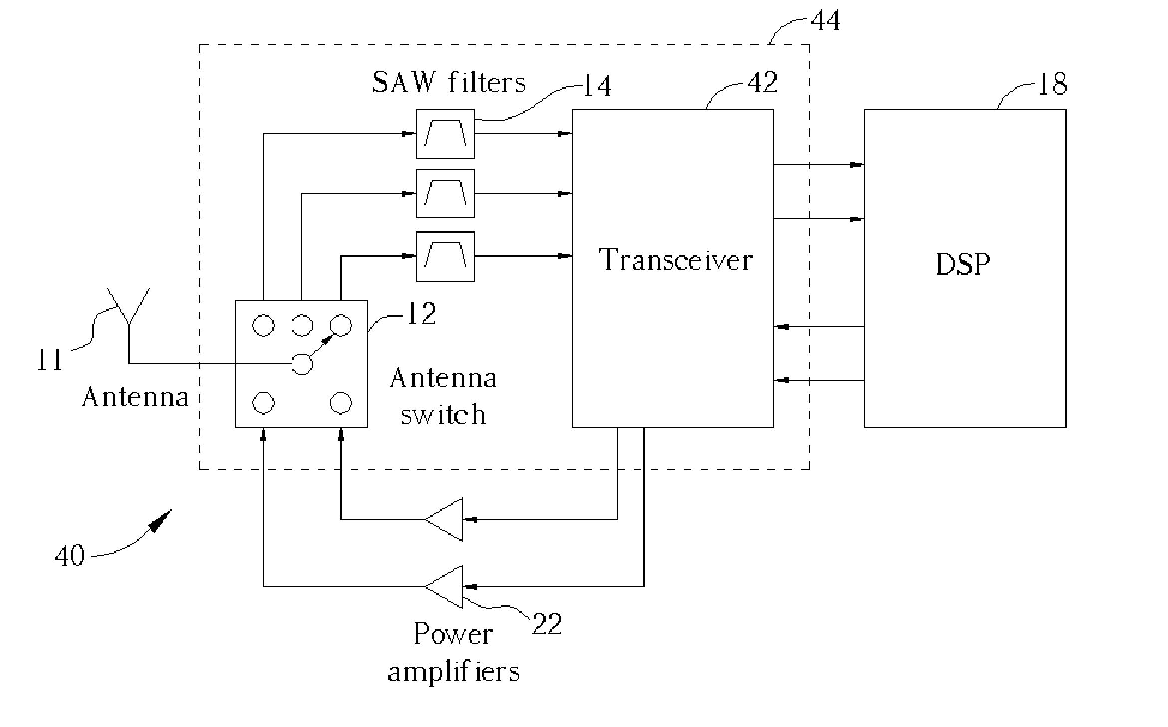
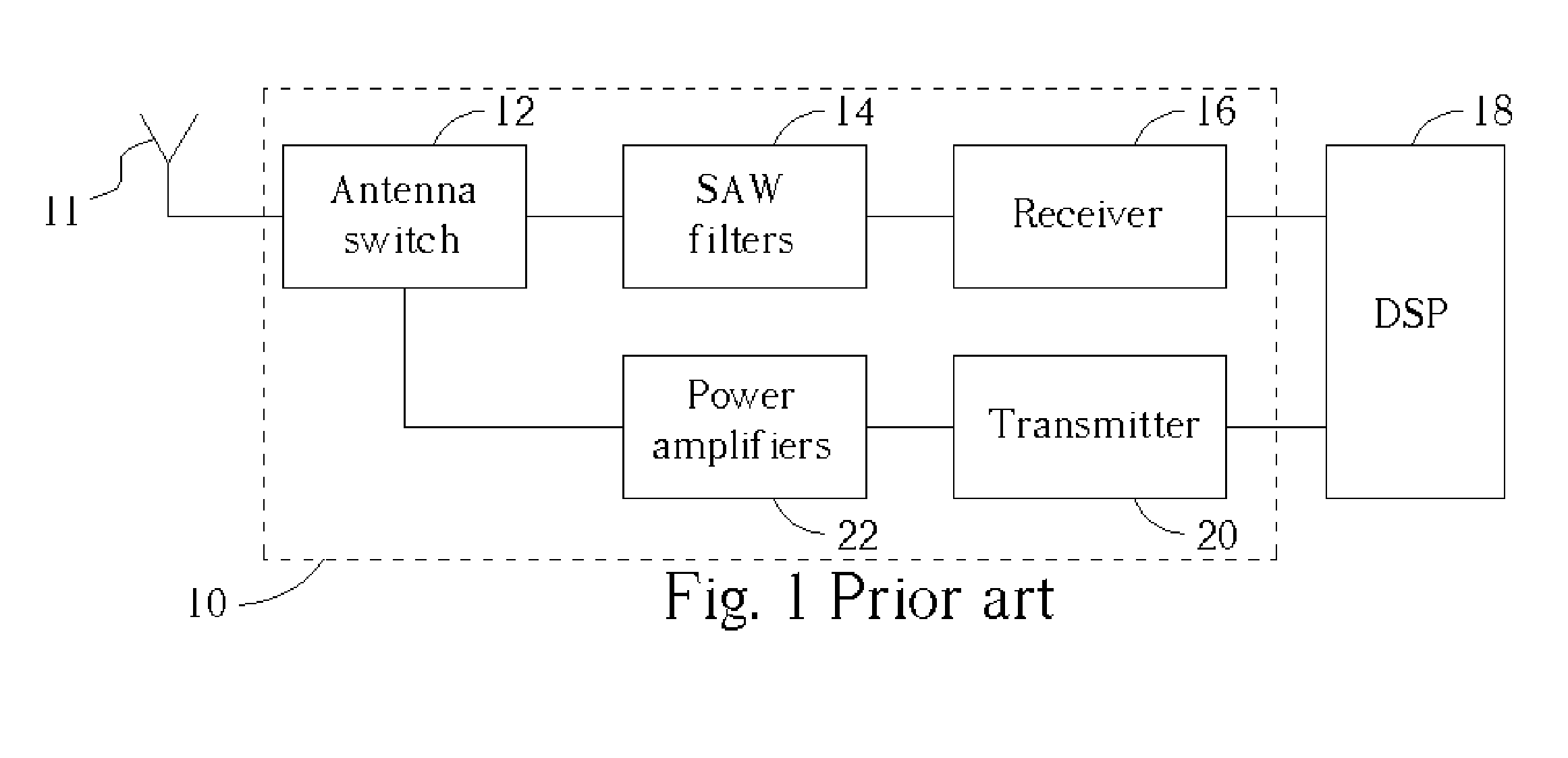
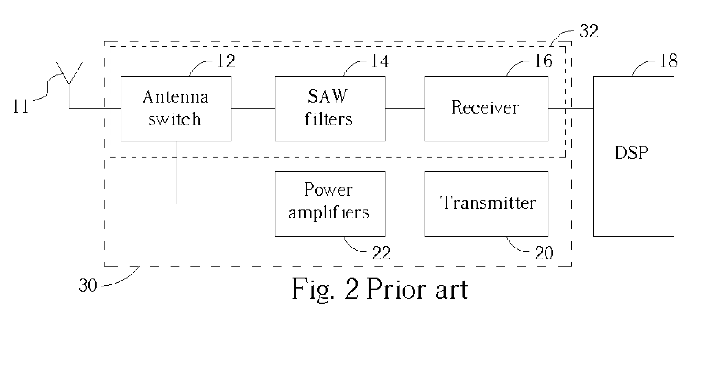
[0019] Please refer to FIG. 2 and FIG. 3. FIG. 3 is a functional block diagram of an RF communication module 40 according to the present invention. The difference between the present invention RF communication module 40 and the prior art RF communication module 30 shown in FIG. 2 is the integration of an RF transceiver IC 42 in a RF transceiver module 44. The RF transceiver IC 42 combines both the receiver 16 and the transmitter 20 of the prior art RF communication module 30. The RF communication module 40 comprises the RF transceiver module 44, and a set of power amplifiers 22. The RF transceiver module 44 comprises an antenna switch 12, a set of SAW filters 14, and the RF transceiver IC 42.

[0020] When the RF communication module 40 receives RF signals from an external antenna 11, the antenna switch 12 is switched such that the received RF signals pass from the antenna 11 to the SAW filters 14 through the antenna switch 12. The received RF signals are then filtered by the SAW filt...


PUM


Abstract

An RF transceiver module for wireless communication devices includes a multi-layered substrate, an RF transceiver IC mounted on the multi-layered substrate for receiving and transmitting voice or data signals, at least one band selection filter mounted on the multi-layered substrate for filtering received RF signals, an antenna switch integrated in the multi-layered substrate which can be switched to transmit RF signals generated by the power amplifiers to the external antenna or to receive RF signals from an external antenna to the RF transceiver IC through the band selection filter, a plurality of passive devices embedded in the multi-layered substrate, and wiring embedded in the multi-layered substrate for electrically connecting the passive devices, the RF transceiver IC, and the band selection filter.

Description

BACKGROUND OF INVENTION [0001] 1. Field of the Invention [0002] The present invention relates to an RF transceiver module, and more specifically, to an RF transceiver module formed in a multi-layered ceramic with an RF transceiver IC. [0003] 2. Description of the Prior Art [0004] Radio frequency (RF) communication modules are commonly used in wireless communication devices such as cellular phones. Typically, RF communication modules are capable of transmitting and receiving over multiple bands, with dual-band and tri-band RF communication modules being the most popular. [0005] Please refer to FIG. 1. FIG. 1 is a functional block diagram of a prior art RF communication module 10 of a wireless communication device. The RF communication module 10 comprises an antenna switch 12, a set of SAW filters 14, and a receiver 16. When the RF communication module 10 receives RF signals from an external antenna 11, the antenna switch 12 is switched such that the RF signals pass from the antenna 1...

Claims


Application Information

Patent Timeline
Patent Type & Authority Applications(United States)
IPC IPC(8): H04B1/38
CPCH04B1/38
Inventor LI, KO-MAILIN, YO-SHENLIU, CHIEN-CHANG
Owner CHI MEI COMM SYST INC
Why Eureka
Try Eureka