Insulated synchronous rectification dc/dc converter

a synchronous rectification and converter technology, applied in the direction of dc-dc conversion, climate sustainability, power conversion systems, etc., can solve the problems of abnormal operation of synchronous rectification transistors, inability to measure control time with high precision, etc., and achieve the effect of uniform characteristics and reduced circuit area

Active Publication Date: 2016-09-08
ROHM CO LTD
View PDF5 Cites 33 Cited by
  • Summary
  • Abstract
  • Description
  • Claims
  • Application Information

AI Technical Summary

Benefits of technology

[0051]By monolithically integrating the circuit on a single chip, such an arrangement allows the circuit area to be reduced, and allows the circuit elements to have uniform characteristics.

Problems solved by technology

With the secondary-side controller 300r having such a SET terminal, if a short circuit (short circuit to a power supply or otherwise to the ground) or otherwise an open circuit occurs in the SET terminal due to dust or a fault in the mounting of the SET terminal, such an arrangement is not capable of measuring the control time with high precision.
This leads to an abnormal operation of the synchronous rectification transistor M2.

Method used


Image

  • Insulated synchronous rectification dc/dc converter
  • Insulated synchronous rectification dc/dc converter
  • Insulated synchronous rectification dc/dc converter

Examples


first embodiment

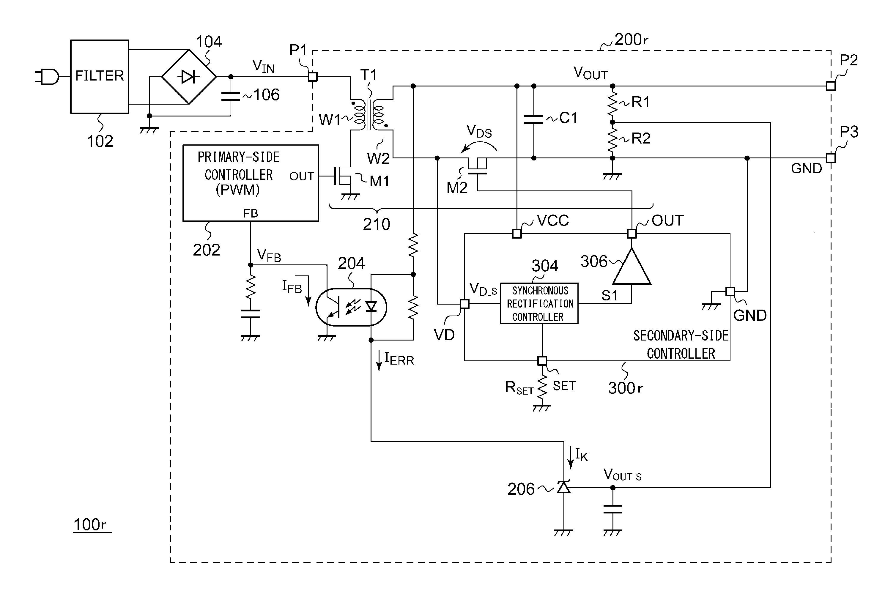
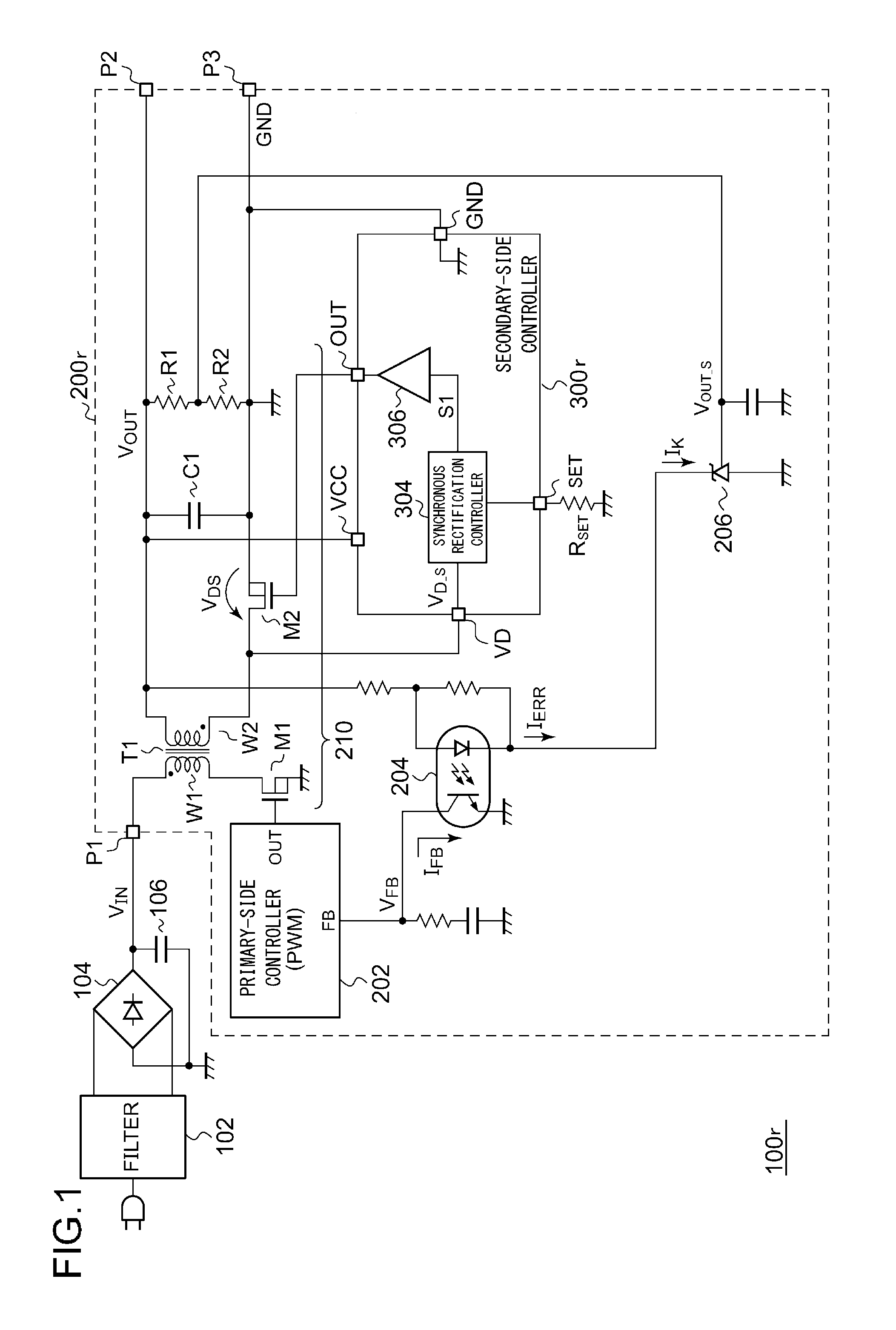
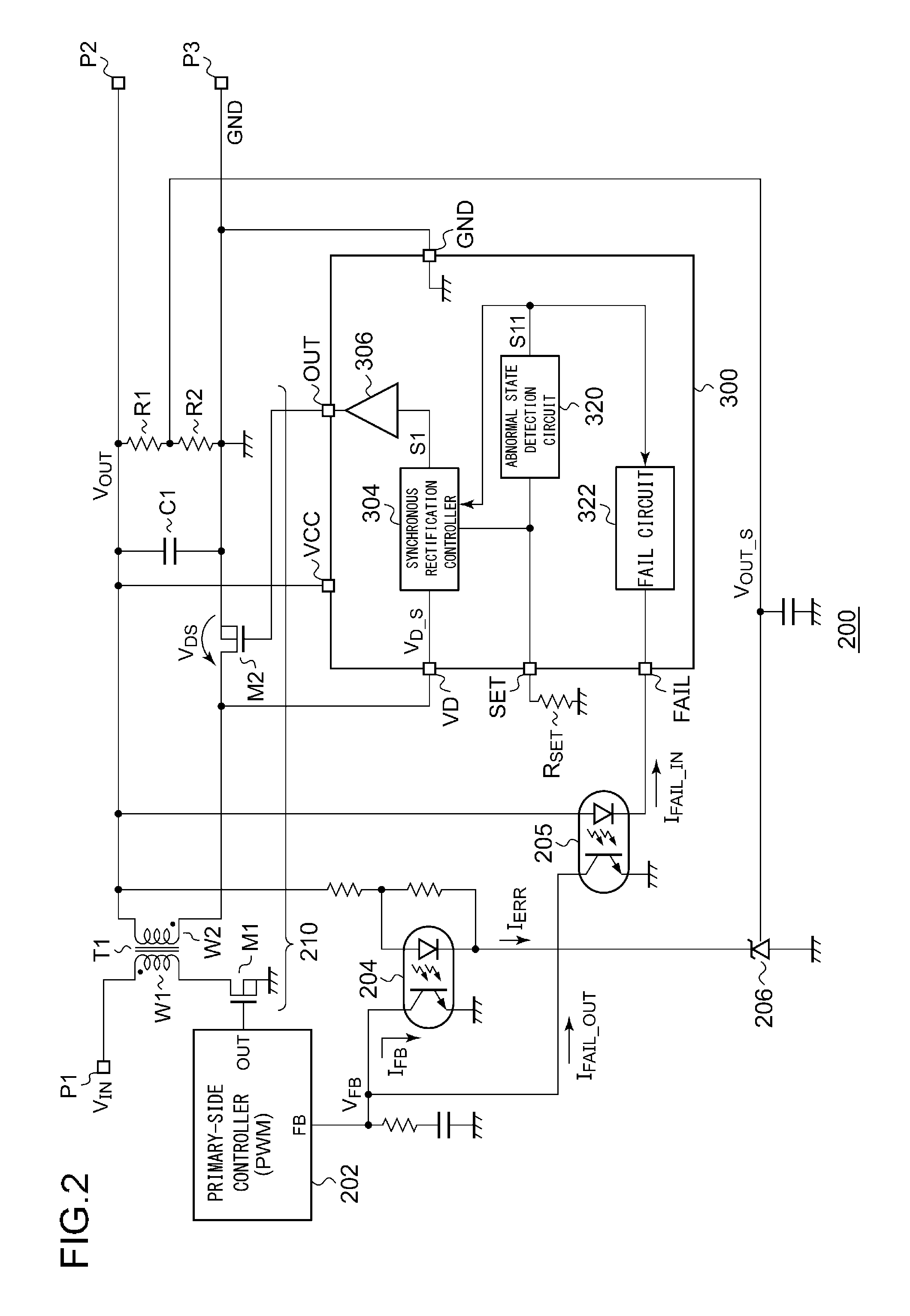
[0083]FIG. 2 is a circuit diagram showing a DC / DC converter 200 including a secondary-side controller 300 according to a first embodiment. The DC / DC converter 200 is applicable to the AC / DC converter in the same way as with the DC / DC converter 200r shown in FIG. 1. Also, the DC / DC converter 200 has the same basic configuration as that of the DC / DC converter 200r shown in FIG. 1.

[0084]The secondary-side controller 300 includes a power supply (VCC) terminal, a switching output (OUT) terminal, a drain (VD) terminal, and a ground (GND) terminal. The secondary-side controller 300 is configured as a function IC (Integrated Circuit) integrally formed on a single semiconductor substrate. The secondary-side controller 300 is housed in a single package together with the synchronous rectification transistor M2. That is to say, the secondary-side controller 300 and the synchronous rectification transistor M2 are monolithically integrated as a single module.

[0085]A DC voltage (here, the output v...

second embodiment

[0110]FIG. 5 is a DC / DC converter 200c including a secondary-side controller 300c according to a second embodiment. The secondary-side controller 300c has the same configuration as that of the secondary-side controller 300 shown in FIG. 2 except that a shunt regulator 206 is built into the secondary-side controller 300c. The shunt regulator 206 includes a transistor M3 and an error amplifier 207. The voltage detection signal VOUT_S is input to the input terminal (SH_IN) of the shunt regulator 206. The error amplifier 207 amplifies the difference between the voltage detection signal VOUT_S and the reference voltage VREF. The transistor M3 is connected to the output terminal (SH_OUT) of the shunt regulator 206. The output VERR of the error amplifier 207 is input to the gate of the transistor M3. In a case in which the transistor M3 is configured as a P-channel MOSFET or otherwise a PNP bipolar transistor, the error amplifier 207 may preferably be arranged such that its inverting input...

third embodiment

[0112]FIG. 6 is a circuit diagram showing a DC / DC converter 200d including a secondary-side controller 300d according to a third embodiment. A shunt regulator 206 is built into the secondary-side controller 300d, as with a configuration shown in FIG. 5. When the detection signal S11 is asserted, a fail circuit 322d drives the feedback photocoupler 204 connected to the SH_OUT terminal.

[0113]For the secondary-side controller 300d, it can be understood that the SH_OUT terminal also provides the same effect as that provided by the FAIL terminal, and that the feedback photocoupler 204 provides the same effect as that provided by the fail notification photocoupler 205.

[0114]Next, description will be made regarding a specific example configuration of the secondary-side controller 300. It should be noted that the present invention encompasses various arrangements derived based on the first through third embodiments. That is to say, the present invention is not restricted to such a specific ...


PUM


Abstract

An external circuit element RSET is connected in use to an SET terminal. A synchronous rectification controller generates a pulse signal S1 based on a control time determined according to the state of the SET terminal. A driver switches on and off the synchronous rectification transistor according to the pulse signal S1. An abnormal state detection circuit is capable of detecting an open-circuit state and/or a short-circuit state that can occur in the SET terminal. When the abnormal state detection circuit detects such an open-circuit state and/or short-circuit state, the abnormal state detection circuit asserts a detection signal S11. When the detection signal S11 is asserted, a primary-side controller arranged on the primary side of the DC/DC converter is instructed to suspend the switching operation of a switching transistor.

Description

CROSS-REFERENCE TO RELATED APPLICATIONS[0001]This application is based upon and claims the benefit of priority from the prior Japanese Patent Application No. 2015-041611, filed Mar. 3, 2015, the entire contents of which are incorporated herein by reference.BACKGROUND OF THE INVENTION[0002]1. Field of the Invention[0003]The present invention relates to an insulated synchronous rectification DC / DC converter.[0004]2. Description of the Related Art[0005]Various kinds of consumer electronics devices such as TVs, refrigerators, etc., each operate receiving commercial AC electric power from an external circuit. Also, electronic devices such as laptop computers, cellular phone terminals, and tablet PCs are each configured to operate using commercial AC electric power, and / or to be capable of charging a built-in battery using such commercial AC electric power. Such consumer electronics devices and electronic devices (which will collectively be referred to as “electronic devices” hereafter) e...

Claims


Application Information

Patent Timeline
Patent Type & Authority Applications(United States)
IPC IPC(8): H02M3/335
CPCH02M3/33523H02M1/32H02M3/33592Y02B70/10
Inventor KIKUCHI, HIROKISHIMIZU, RYO
Owner ROHM CO LTD
Why Eureka
Try Eureka