Display system and lighting device used therein

a technology of lighting device and display system, which is applied in the direction of semiconductor lamp usage, lighting and heating apparatus, electroluminescent light sources, etc., can solve the problems of increasing parts cost, arrangement and heat radiation, and achieve the effect of accurate detection of the luminiferous level of each led, increasing the number of photoelectric conversion elements, increasing parts cost, and increasing heat radiation

Inactive Publication Date: 2006-06-29
HITACHI LTD
View PDF6 Cites 36 Cited by
  • Summary
  • Abstract
  • Description
  • Claims
  • Application Information

AI Technical Summary

Benefits of technology

[0006] However, in order to accurately detect the luminiferous level of each LED, it is necessary to increase the number of the photoelectric conversion elements. This would create new problems in increased parts cost, arrangement and heat radiation.
[0007] Hence a nee

Problems solved by technology

This would create new problems in increased

Method used


Image

  • Display system and lighting device used therein
  • Display system and lighting device used therein
  • Display system and lighting device used therein

Examples


Embodiment Construction

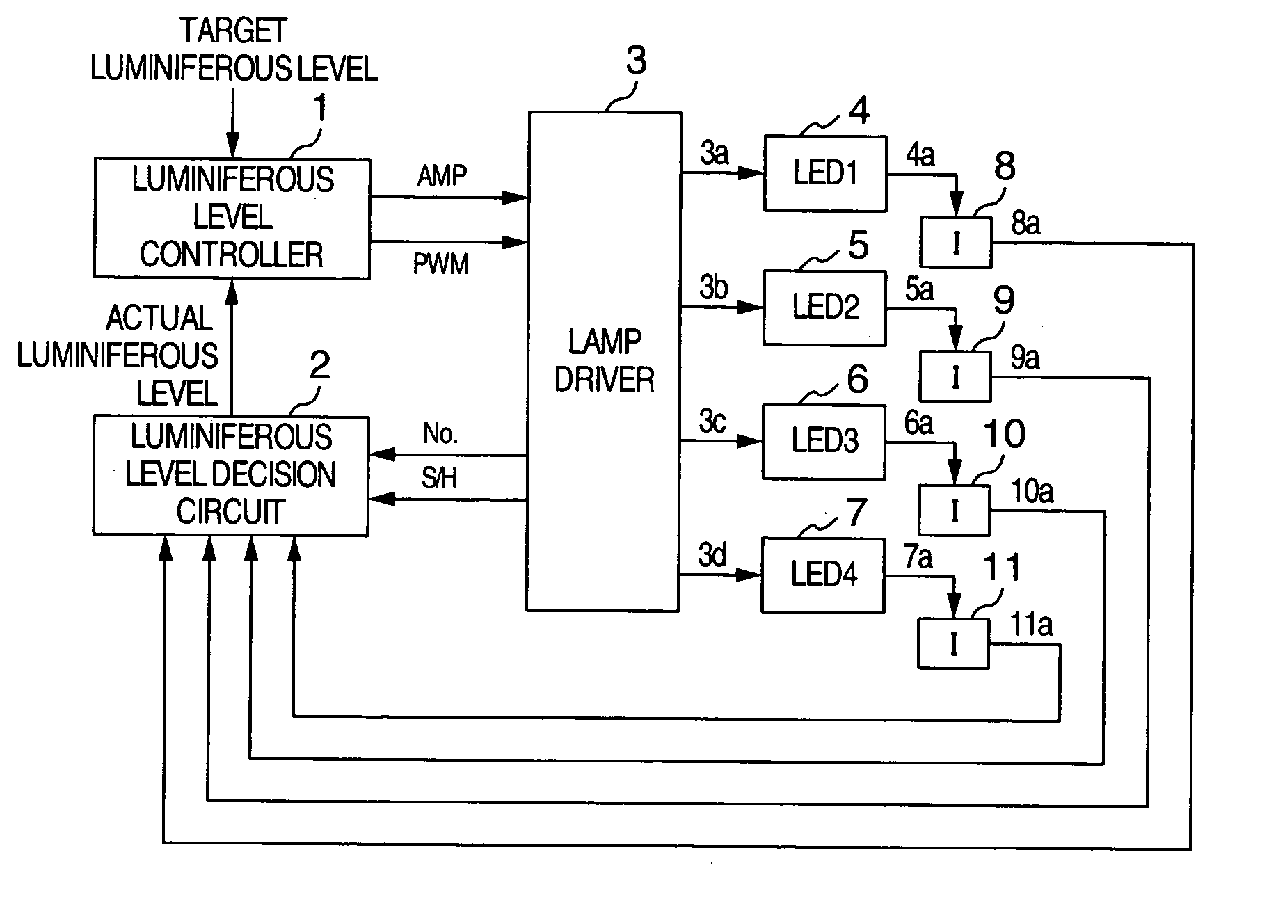
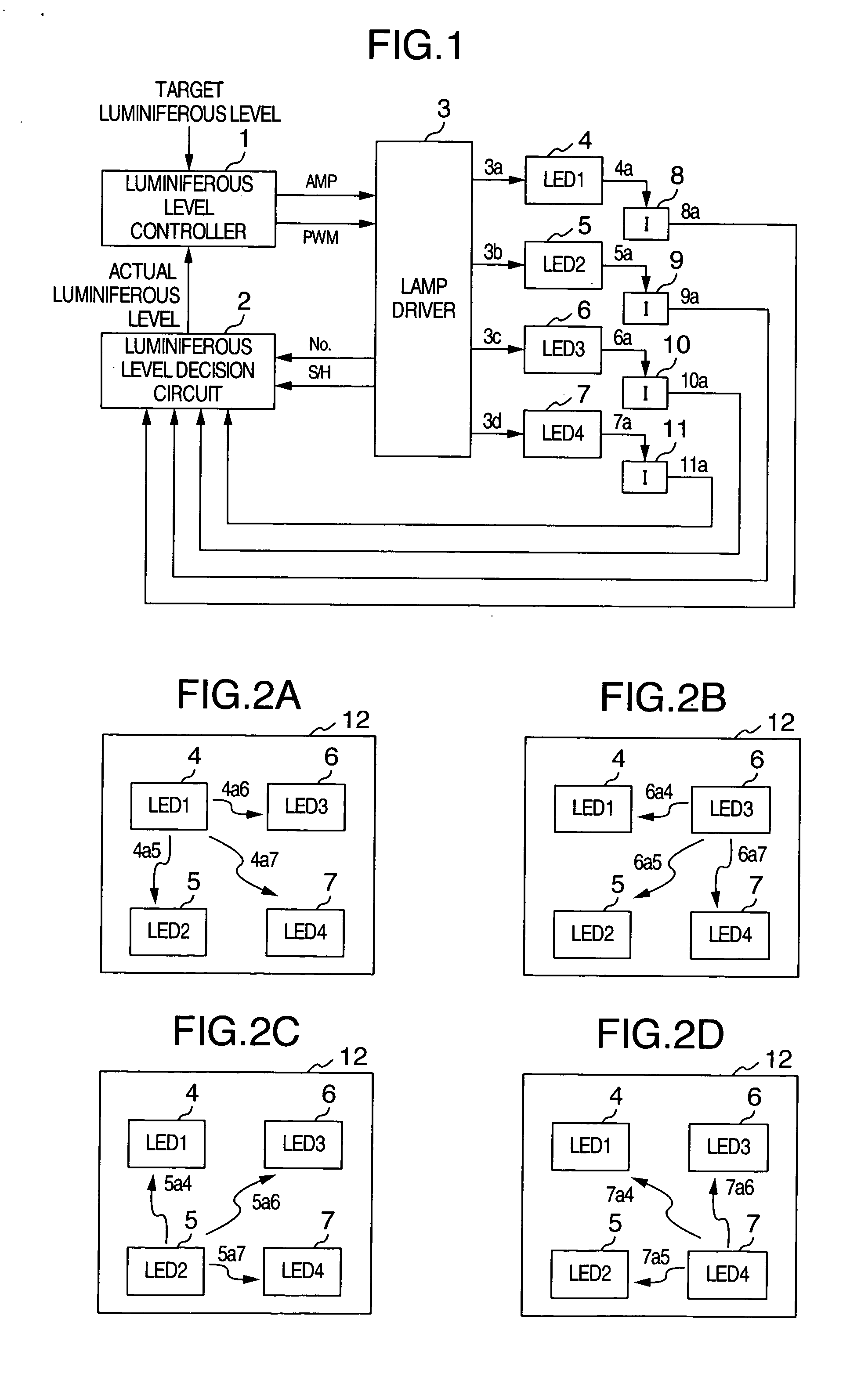
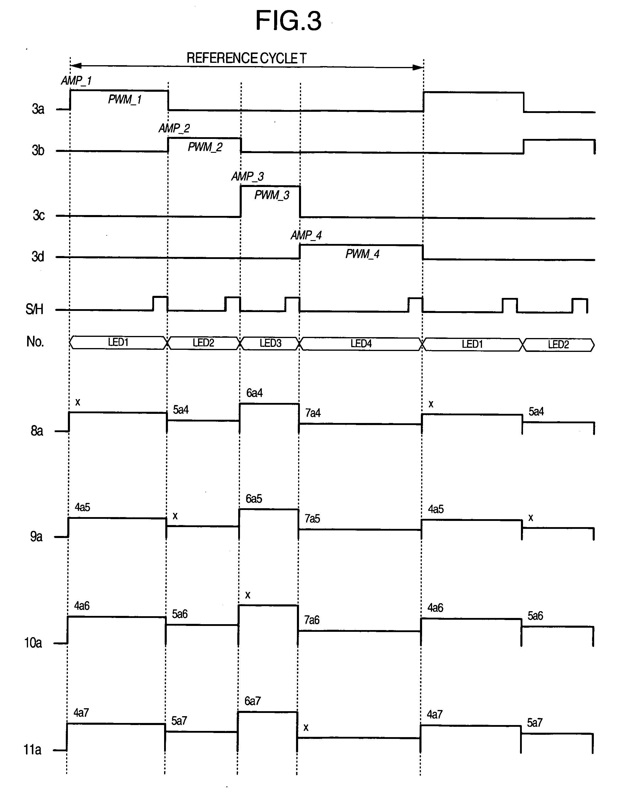
[0023]FIG. 1 is a block diagram showing a lighting system according to a first embodiment of the present invention. FIG. 2 is a layout map showing an example of layout method of light emitting devices of the lighting system according to the present invention. FIG. 3 is a signal wave form showing the operation timing and the operation state in each processing section.

[0024] Here, as the light emitting device in this embodiment, explanation will be give on the case of LED. Moreover, in this embodiment, the luminiferous efficiency and the luminiferous level as the luminiferous performance of the LED is not to be limited to particular ones and may be any if a luminiferous level required for the system can be obtained. Moreover, in this embodiment, the light wavelength component emitted by the LED is not limited to a particular one but may be any as long as the LED is so configured that a white component and specific color components of red, blue, green, and the like may be obtained in ...


PUM


Abstract

In a drive circuit of light emission device arrays each having at least one light emission device, at least one of the light emission diode arrays is pulse-driven with a pulse of phase different from the other light emission device arrays. While the at least one light emission device array driven with a different phase is OFF, a processing circuit acquires the luminiferous level of each of the other light emission device arrays by using the at least one light emission device array which is OFF as a light reception device. Furthermore, a control circuit controls the drive level of the drive circuit for the light emission device arrays which are ON.

Description

INCORPORATION BY REFERENCE [0001] The present application claims priorities from Japanese applications JP2004-378763 filed on Dec. 28, 2004 and JP2005-135502 filed on May 9, 2005, the contents of both of which are hereby incorporated by reference into this application. BACKGROUND OF THE INVENTION [0002] The present subject matter relates to techniques and equipment to perform image formation by applying a light flux from a light source to a transmissive or reflective liquid crystal panel or a display panel such as a reflection micromirror device and in particular, to a lighting system as a light source used in a display system. [0003] Recently, with increase of luminiferous efficiency of a light emitting diode (hereinafter, referred to as LED), applications of LEDs to high-luminance lighting systems have been growing. However, the LED has problems that the luminiferous level is changed much as the time elapses and irregularities of the luminiferous characteristics are great among LE...

Claims


Application Information

Patent Timeline
IPC IPC(8): F21V7/04H01L33/08
CPCH05B33/0818H05B33/0866H05B33/0869Y02B20/346H05B45/22H05B45/24Y02B20/30
Inventor KOBORI, TOMOKIOUCHI, SATOSHIIMAHASE, TAROMARUYAMA, ATSUSHI
Owner HITACHI LTD
Why Eureka
Try Eureka