Antenna

a technology of antennas and earthings, applied in the direction of resonant antennas, antenna earthings, radiating elements, etc., can solve the problems of relatively low pag figures, and achieve the effects of less power, better able to receive signals, and longer talk time/battery li

Inactive Publication Date: 2006-06-13
META PLATFORMS INC
View PDF8 Cites 47 Cited by
  • Summary
  • Abstract
  • Description
  • Claims
  • Application Information

AI Technical Summary

Benefits of technology

[0011]An antenna according to embodiments of the invention has a higher PAG figure than an antenna consisting of only one of the two elements making up the antenna. A higher PAG contributes directly to longer talk time / battery life, as less power needs to be transmitted from the antenna to achieve a desired signal strength at a given remote point.
[0012]Such performance also means that such an antenna, operating in receive mode, is better able to receive signals of a given strength, than an antenna having a lower PAG figure.

Problems solved by technology

A problem with prior art antennas is their relatively low PAG figures.

Method used


Image

  • Antenna
  • Antenna
  • Antenna

Examples


Embodiment Construction

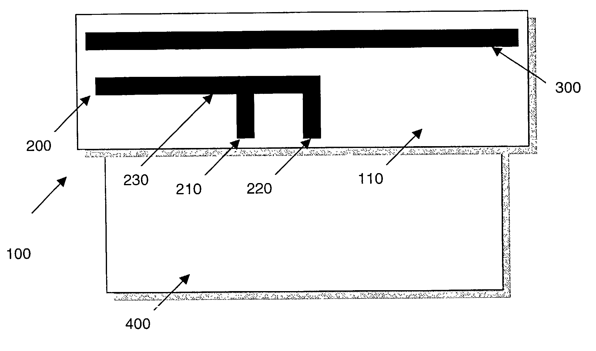
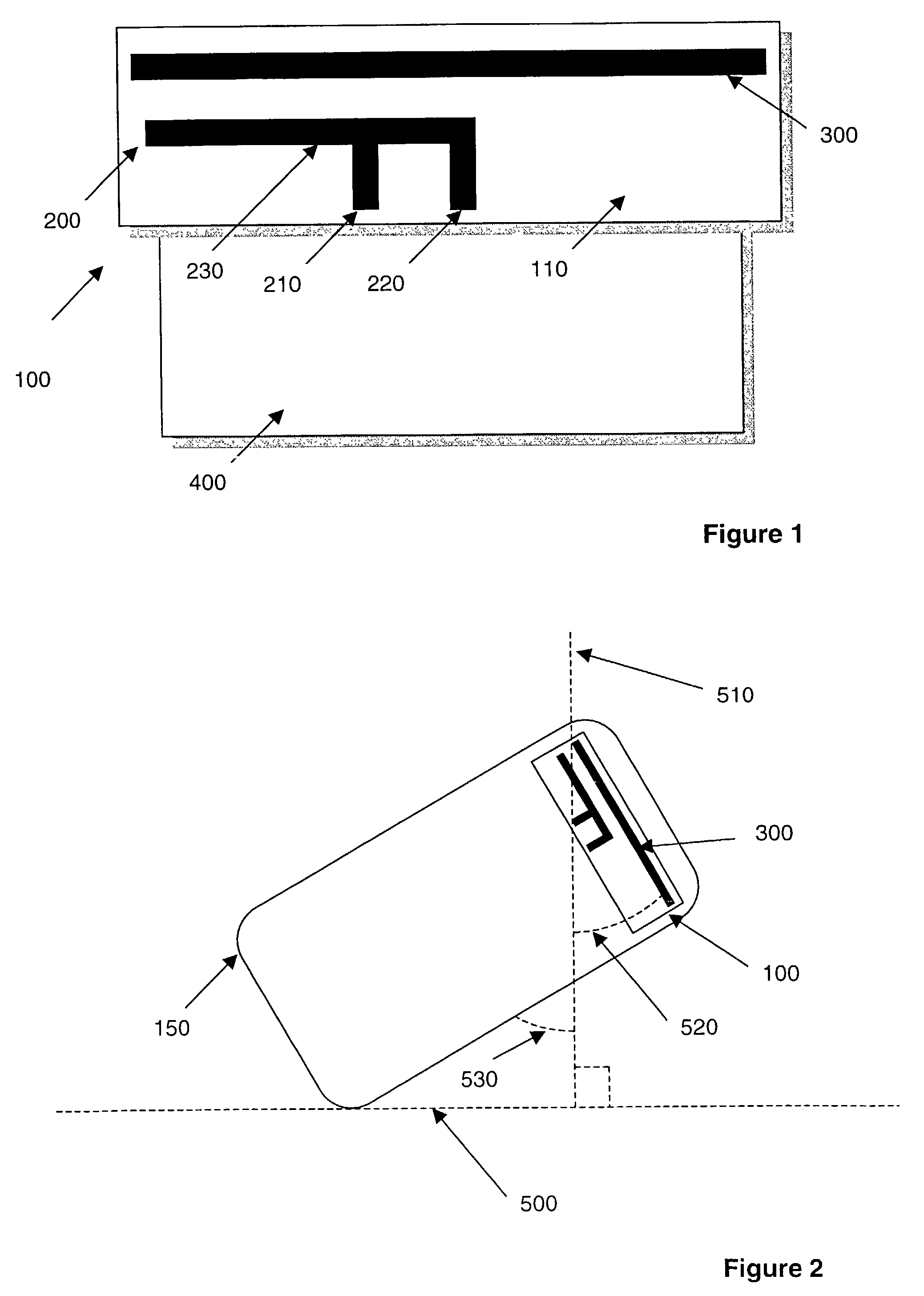
[0028]FIG. 1 shows a plan view of an antenna 100 according to an embodiment of the invention. The antenna 100 is disposed on a substrate 110. The substrate comprises an insulating material. The antenna is positioned slightly above a ground plane 400. The ground plane is formed from a circuit board housing components of a portable telephone. The antenna 100 may be formed integrally with the ground plane 400.

[0029]The antenna 100 comprises two distinct antenna elements 200, 300 arranged to be coplanar. Elements 200 and 300 are created on the substrate using standard techniques. Such techniques may include printing using a suitable conductive ink, or deposition, or using a metal removing process such as etching.

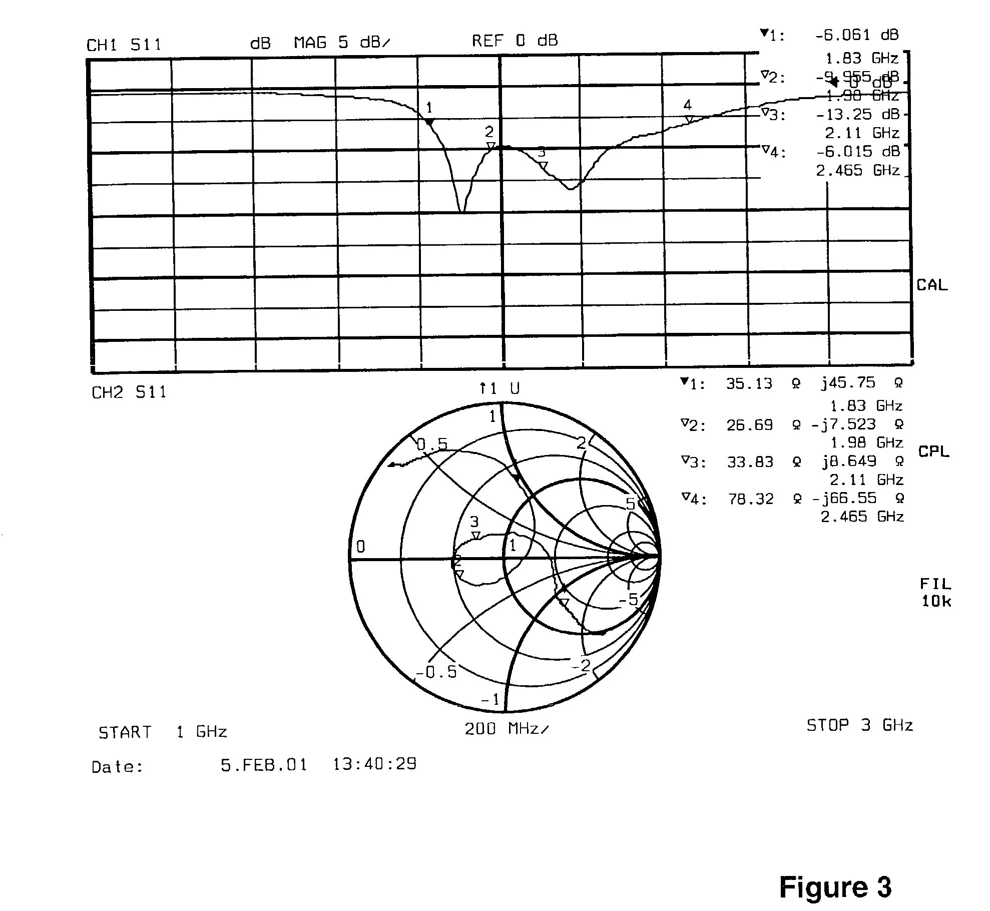
[0030]Element 200 is a Planar Inverted F Antenna (PIFA). It is a conventional quarter wavelength (λ / 4) PIFA and comprises a feed point 210, a ground stub connection 220 and a radiating portion 230. ‘Quarter wavelength’ refers to the wavelength of intended operation of the antenn...


PUM


Abstract

An antenna is disclosed. The antenna has a first element including an unbalanced antenna with a feed point, and a second element. The second element has a spaced relationship with the first element, and includes a balanced antenna arranged to be electromagnetically coupled to the first element. Embodiments of the invention exhibit relatively high Pattern Averaged Gain (PAG).

Description

BACKGROUND OF THE INVENTION[0001]This invention relates to an antenna. The antenna has a relatively high Pattern Averaged Gain (PAG) figure, and finds particular utility in portable wireless devices such as portable telephones.[0002]PAG is one of several metrics that can be used to characterise antennas. All antennas radiate energy, to a greater or lesser degree, in one or more directions. PAG is one measure of the average transmission characteristics averaged over a full 360° surrounding the antenna. The better the PAG figure, the better the overall transfer of energy from the transmitter via the antenna.[0003]PAG is normally calculated to take into account the dominant polarization intended for a given antenna. For instance, in mobile telephony, the antenna at a Base Station (BS) is generally vertically polarized, and in order to optimize performance, the antenna at the Mobile Station (MS) should be vertically polarized also. However, different people hold their MSs differently, a...

Claims


Application Information

Patent Timeline
Patent Type & Authority Patents(United States)
IPC IPC(8): H01Q1/38H01Q1/24H01Q9/04
CPCH01Q1/243H01Q9/0421H01Q9/0414
Inventor ZHENG, MINGSHAPTER, HUGH
Owner META PLATFORMS INC
Why Eureka
Try Eureka