Beam scanning microstrip planar reflection array antenna based on microcrystal material and fabrication method of beam scanning microstrip planar reflection array antenna

A planar reflection array and beam scanning technology, applied in antennas, antenna arrays, and devices for manufacturing antenna arrays, etc., can solve the problems of low application frequency, low DC power consumption, and low power capacity, and achieve large occupied space and communication. The effect of long distance and low loss

Inactive Publication Date: 2017-08-15
UNIV OF ELECTRONICS SCI & TECH OF CHINA
View PDF3 Cites 20 Cited by
  • Summary
  • Abstract
  • Description
  • Claims
  • Application Information

AI Technical Summary

Problems solved by technology

Electronic device tuning technology has fast scanning speed, low bias voltage, and low DC power consumption, but it has technical problems of low power capacity and low application frequency

Method used


Image

  • Beam scanning microstrip planar reflection array antenna based on microcrystal material and fabrication method of beam scanning microstrip planar reflection array antenna
  • Beam scanning microstrip planar reflection array antenna based on microcrystal material and fabrication method of beam scanning microstrip planar reflection array antenna
  • Beam scanning microstrip planar reflection array antenna based on microcrystal material and fabrication method of beam scanning microstrip planar reflection array antenna

Examples


Embodiment 1

[0049] This embodiment provides a beam scanning microstrip planar reflectarray antenna of a microcrystalline material, such as Figure 7 , including a microstrip antenna array, a dielectric plate located below the microstrip antenna array in turn, and a ground plane. The phase-shifting unit connected; the beam scanning device connected to the phase-shifting unit and the feed source connected with the beam scanning device, the feed source is located directly below the microstrip reflective array; the phase-shifting unit is a liquid crystal unit ; The feed source is used to connect the input / output end of the antenna; The beam scanning device is used to provide an external bias voltage of the phase shifting unit.

[0050] The loss angle of the liquid crystal material decreases as the frequency increases and there is no cut-off frequency, which can realize the high-frequency band and low loss of the microstrip planar reflectarray antenna; in addition, the liquid crystal material ha...

Embodiment 2

[0067] On the basis of Embodiment 1, this embodiment further optimizes the design of the antenna element.

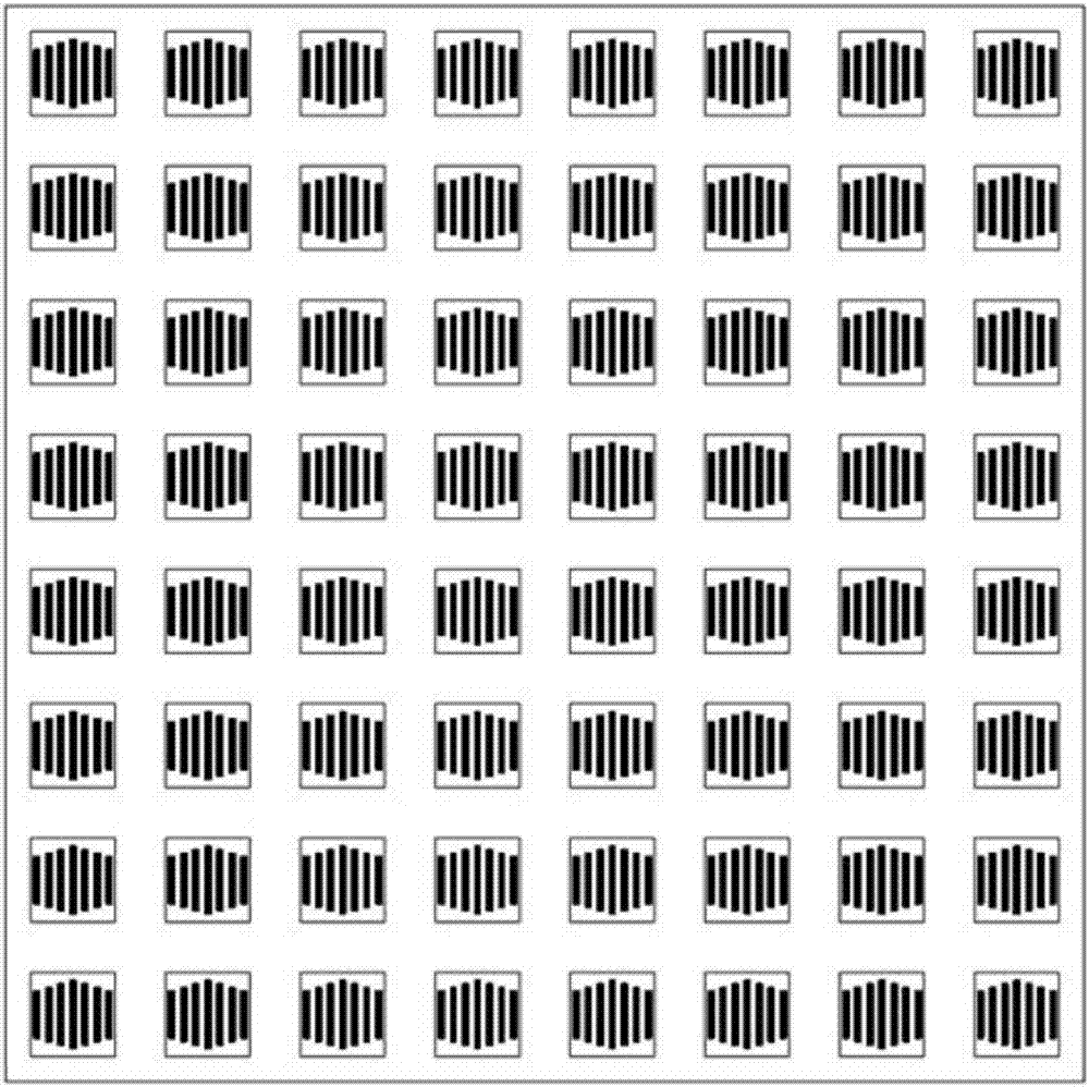
[0068] The traditional variable-size resonant unit obtains the required phase shift by generating resonances with different strengths in the operating frequency band. The phase shift characteristic of the unit itself responds nonlinearly to frequency changes, which is a key factor limiting the operating bandwidth. In order to increase the operating bandwidth of the reflection unit, it is necessary to reduce the frequency sensitivity of the reflection characteristic of the unit to obtain a nearly linear phase shift characteristic. In order to reduce the frequency sensitivity of the reflection characteristic of the unit and expand the bandwidth of the reflection unit, this embodiment adopts the multi-resonance unit technology. Such as image 3 , the array element of the microstrip antenna in this embodiment is a multi-resonance structure unit, including 7 reflection unit ...


PUM


Abstract

The invention relates to a beam scanning microstrip planar reflection array antenna based on a microcrystal material and a fabrication method of the beam scanning microstrip planar reflection array antenna, which are mainly used for solving the technical problems of low power capacity and low working frequency band in the prior art. The beam scanning microstrip planar reflection array antenna comprises phase shift units, beam scanning devices and a feeding source, wherein the phase shift units are arranged right below a microstrip reflection array and are in contact with the microstrip reflection array, the beam scanning device are correspondingly connected with the phase shift units, the feeding source is connected with the beam scanning device and is arranged right below the microstrip reflection array, the phase shift units are liquid crystal units and are used for connecting an input / output end of the antenna, and the beam scanning devices are used for providing external bias for the phase shift units. By the technical scheme, the problem is solved very well, and the beam scanning microstrip planar reflection array antenna can be used for a communication and radar system.

Description

technical field [0001] The invention relates to the technical field of antennas, in particular to a beam-scanning microstrip planar reflection array antenna based on microcrystalline materials and a manufacturing method. Background technique [0002] The high-gain beam scanning antenna has the advantages of strong anti-interference, long communication distance, large amount of communication information, and the ability to track targets in real time. It is widely used in radar navigation tracking, satellite communication, and large-scale deep space exploration. High-gain beam scanning antennas include parabolic reflector antennas, phased array antennas, and microstrip planar reflectarray antennas. Parabolic reflector antennas can realize the dynamic scanning function of electromagnetic beams through mechanical rotation, but the scanning speed is slow, and the mechanical metal devices are heavy and occupy a lot of space. Disadvantages such as large space size; phased array ant...

Claims


Application Information

Patent Timeline
Patent Type & Authority Applications(China)
IPC IPC(8): H01Q3/34H01Q15/14H01Q21/00
CPCH01Q15/14H01Q3/34H01Q15/141H01Q21/00H01Q21/0087
Inventor 蒋迪万应禄刘宇鹏丁萍程婕韩默
Owner UNIV OF ELECTRONICS SCI & TECH OF CHINA
Why Eureka
Try Eureka