
Rapid explosion-proof charging gun
A charging gun, fast technology, applied in charging stations, electric vehicle charging technology, circuits, etc., can solve the problems of inconvenient installation and disassembly, low connection efficiency, etc., and achieve improved connection efficiency, high contact reliability, and wide contact surface Effect
- Summary
- Abstract
- Description
- Claims
- Application Information
AI Technical Summary
Problems solved by technology
Method used
Image

Examples
Embodiment Construction
[0031] The rapid explosion-proof charging gun of the present invention will be described in further detail below in conjunction with specific drawings.
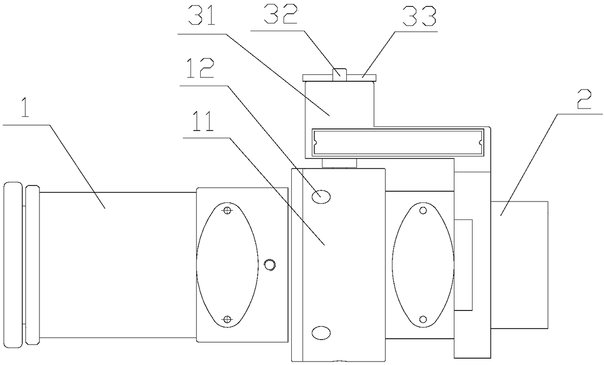
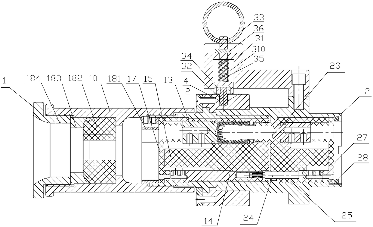
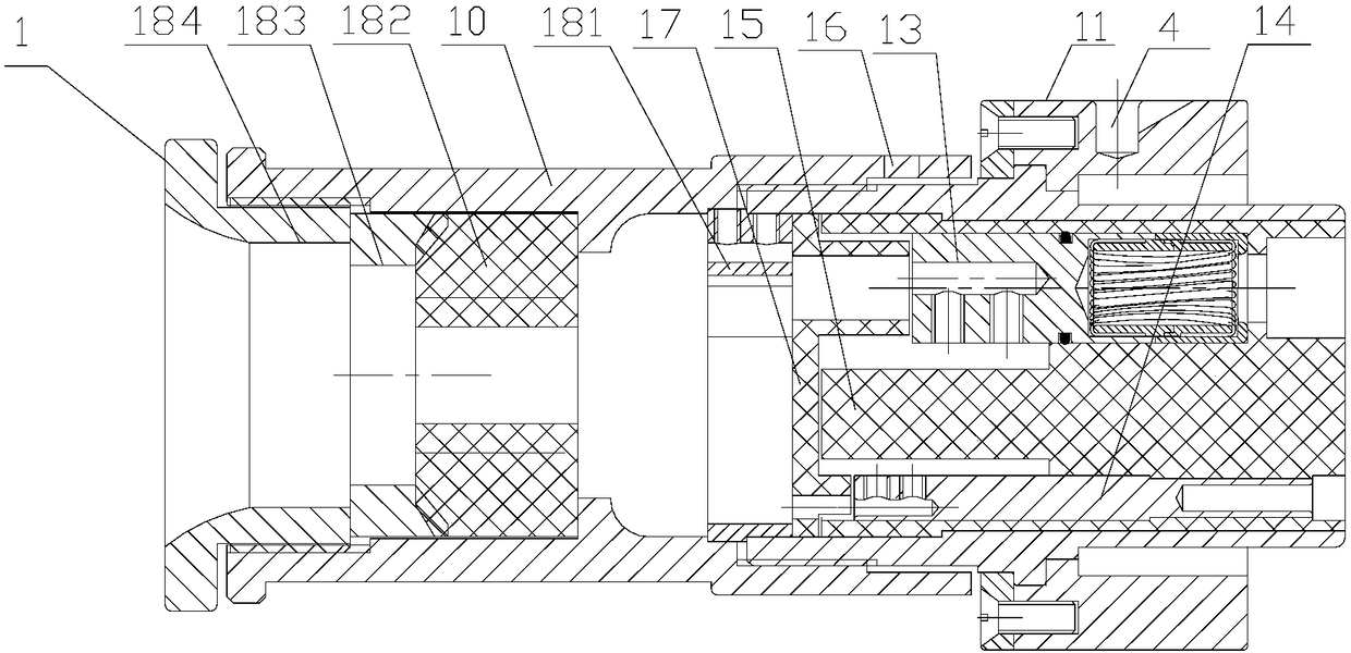
[0032] like figure 1 and figure 2 As shown, it is a fast explosion-proof charging gun of the present invention, including a plug assembly 1 and a socket assembly 2, such as Figure 5 As shown, the socket assembly 2 includes a self-locking structure 3, and the self-locking structure 3 includes a mounting plate 31, a pull rod 32, a pull ring 33 arranged at the rear of the pull rod 32, and a stopper 34 arranged at the front of the pull rod 32 , and the spring 35 sleeved outside the pull rod 32, the inside of the mounting plate 31 is a groove 310, the groove 310 is provided with a through hole, the pull rod 32 passes through the through hole and can be opposite to the The through hole slides back and forth, the stopper 34 can slide back and forth relative to the groove 310 of the mounting plate 31, one end of the spring 35 abu...
PUM
 Abstract
Description
Claims
Application Information