Rapid 3D printing apparatus and method

A 3D printing and fast technology, applied in the field of 3D printing, can solve the problems of difficulty in controlling the positioning accuracy of nozzles, difficulty in printing suspended parts, and insufficient strength of parts, and achieve the effects of overcoming the difficulty of printing in suspended parts, reducing air and improving strength

Active Publication Date: 2018-07-24
WUHAN E YOUCAN MEDICAL TECH CO LTD
View PDF9 Cites 4 Cited by
  • Summary
  • Abstract
  • Description
  • Claims
  • Application Information

AI Technical Summary

Problems solved by technology

This solution looks perfect on paper, but there are the following technical problems. 1. The problem of material clogging. After replacing the nozzle, the plastic in the nozzle is easy to block the nozzle due to dust entering after cooling.
2. In the process of frequent replacement of nozzles, error accumulation is prone to occur
3. It is difficult to control the positioning accuracy of nozzle replacement in a narrow space
[0004] Existing plastic 3D printing devices still have the problem of insufficient strength of the printed parts, and the problem that the suspended parts are difficult to print

Method used


Image

  • Rapid 3D printing apparatus and method
  • Rapid 3D printing apparatus and method
  • Rapid 3D printing apparatus and method

Examples


Embodiment 1

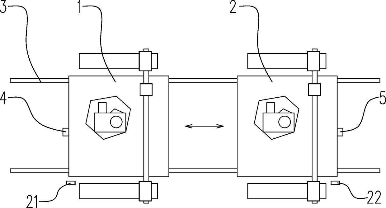
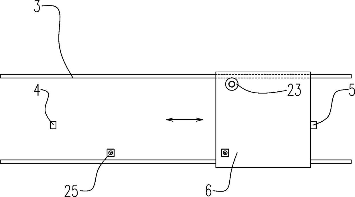
[0038] Such as Figure 1~4 Among them, a fast 3D printing device includes at least two 3D printing devices, at least one synchronous positioning plate 6, a guide device for guiding the synchronous positioning plate 6 is provided between the 3D printing devices, and at the position of each 3D printing device A positioning device for positioning the synchronous positioning plate 6 is provided;

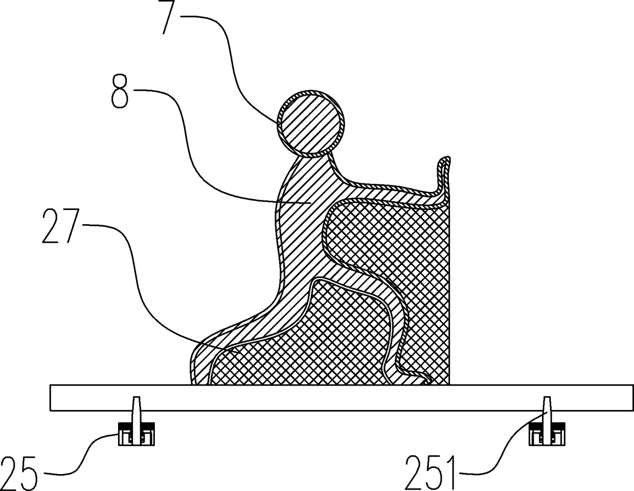
[0039] The 3D printing device is provided with nozzles of different diameters, corresponding to the part outline part 7 and the part filling part 8 respectively. Through the above structure, the part contour part 7 is printed at the position of the first 3D printing device 1, and then the synchronization positioning plate 6 is moved along the guide device to the second 3D printing device 2 to print the part filling part 8, thereby greatly speeding up the printing speed.

[0040] The preferred solution is as figure 1 , 2 Among them, the guide device is a track 3, the synchronous positi...

Embodiment 2

[0047] Different from Example 1, another optional scheme such as Figure 6~9 In the above, the 3D printing device is arranged along the circumference, the synchronization positioning plate 6 is positioned and installed on the rotatable turntable 11 , and the positioning device is a circumferential positioning device 16 .

[0048] The preferred solution is as Figure 8 Among them, the said circumferential positioning device 16 is provided with a limit rod 164 driven by an electromagnet 161, a spring 163 is arranged on the limit rod 164, the limit rod 164 is fixedly connected with the armature 162, and on the turntable 11 A turntable limiting groove 111 engaged with the limiting rod 164 is provided, and the position of the turntable limiting groove 111 on the turntable 11 corresponds to the position of the 3D printing device. The position of the turntable 11 on the circumference is precisely positioned by the circumferential positioning device 16 .

[0049] The preferred solut...

Embodiment 3

[0054] Existing 3D printed plastic parts have the problem of insufficient strength. The inventor sliced ​​the part and observed under a microscope and found that there are many interlayer bubbles on the part, and the bonding interface between the droplets is relatively clear.

[0055] On the basis of Examples 1 and 2, the preferred scheme is as Figure 9 Among them, a sealing cover body 19 is provided outside all 3D printing devices, and the inner cavity of the sealing cover body 19 is connected with a vacuum device; thus, the interlayer air bubbles on the parts are reduced. The relative vacuum can be between -10~-75KPa.

[0056] In a preferred solution, the 3D printing device is also provided with a heating device 20 for heating parts. The heating device in this example is a resistance wire heating device, and the heating temperature is 40 to 80 degrees Celsius.

[0057] By adopting the above scheme, observed under the microscope, the interlayer bubbles are greatly reduced,...


PUM


Abstract

The invention provides a rapid 3D printing apparatus and method. The rapid 3D printing apparatus comprises at least two 3D printing apparatuses, at least one synchronous positioning plate, a guiding apparatus is arranged between the 3D printing apparatuses and used for guiding the synchronous positioning plate, and a positioning apparatus for positioning the synchronous positioning plate is arranged on the position of each 3D printing apparatus; and the 3D printing apparatus is provided with a spray opening of different diameters respectively corresponding to a component outline part and a component filling part. The components are layered according to a given height, an outer outline of each layer is set as a component outline part, and an area between the component outline parts is set as the component filling part; the at least one 3D printing apparatus prints the component outline part of each layer on the synchronous positioning plate, and the synchronous positioning plate is moved to another 3D printing apparatus to print the component filling part; and by virtue of the steps, the rapid 3D printing is realized. By adopting multiple independent 3D printing apparatuses with thespray openings of different diameters, on the premise of ensuring the accuracy, the 3D printing speed of the components can be greatly improved.

Description

technical field [0001] The invention relates to the field of 3D printing, in particular to a fast 3D printing device and method. Background technique [0002] 3D printing technology is a manufacturing technology that combines computer digital technology and manufacturing technology. By layering and stacking, existing production personnel can quickly produce samples, especially for plastic products, which can greatly save the cost of molds and reduce development costs. Existing 3D printing devices are slow to print a part. This is because in order to ensure the accuracy of the parts, the diameter of the nozzle of the 3D printing device needs to be set sufficiently thin, and the thinner diameter of the nozzle is easy to be blocked by impurities in the plastic, and the printing speed is very slow. [0003] In the prior art, there is a multi-nozzle solution to solve this technical problem. For example, Chinese patent document CN104985812 A describes a multi-nozzle mechanism fo...

Claims


Application Information

Patent Timeline
Patent Type & Authority Applications(China)
IPC IPC(8): B29C64/20B29C64/295B29C64/112B29C64/364B33Y30/00B33Y40/00
CPCB33Y30/00B33Y40/00Y02P10/25
Inventor 宋恩民
Owner WUHAN E YOUCAN MEDICAL TECH CO LTD
Why Eureka
Try Eureka