
New material device for catalyst support
A catalyst carrier, equipment and device technology, applied in transportation and packaging, chemical instruments and methods, chemical/physical processes, etc., can solve the problems of affecting processing efficiency, single stirring direction, and low stirring and mixing efficiency
- Summary
- Abstract
- Description
- Claims
- Application Information
AI Technical Summary
Problems solved by technology
Method used
Image

Examples
Embodiment Construction
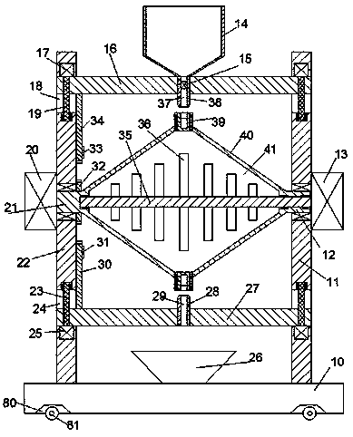
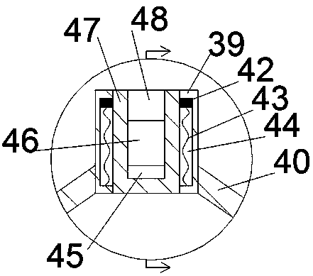
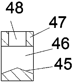
[0019] Such as Figure 1-Figure 4 As shown, a new material equipment device for a catalyst carrier of the present invention includes a base 10, a left support frame 22 and a right support frame 11 fixedly installed on the base 10, and the four corner bottoms of the base 10 are Simultaneously, a mounting groove 80 is provided, in which a roller 81 is rotatably installed, and a barrel 40 is arranged between the left supporting frame 22 and the right supporting frame 11, and a cavity 41 is arranged in the charging barrel 40, so that The left and right turning rods 21 and 12 are respectively arranged at the left and right ends of the outer side of the barrel 40, and the left turning rod 21 and the right turning rod 12 are rotatably installed in the left supporting frame 22 and the right supporting frame 11 respectively. , the left turning rod 21 is power-connected with the first motor 20 fixedly installed on the left end surface of the left supporting frame 22, the cavity 41 is pr...
PUM
 Abstract
Description
Claims
Application Information