Al technical title is built by PatSnap Al team. It summarizes the technical point description of the patent document.
A technology of wire cutters and deep holes, which is applied in the field of wire cutters, can solve problems such as difficult passage of anchor cables and difficulty in putting into drill holes, and achieve the effects of improving reinforcement efficiency, increasing utilization rate, and simple structure
Active Publication Date: 2021-03-30
兖矿能源集团股份有限公司
View PDF4 Cites 0 Cited by
Summary
Abstract
Description
Claims
Application Information
AI Technical Summary
This helps you quickly interpret patents by identifying the three key elements:
Problems solved by technology
Method used
Benefits of technology
Problems solved by technology
For example, in Jining No. 3 Coal Mine, when a narrow coal pillar was left along the goaf roadway for reinforcement with expansion-locking anchor cables, it was discovered through drilling holes that there were abandoned anchor nets and shotcrete supports on the side of the goaf, and most diamond-shaped nets It has not yet been damaged. The two-way reinforced anchor cable needs to pass through the diamond-shaped net to better exert its locking force. The existence of the diamond-shaped net makes it difficult for the anchor cable to pass through the front pocket. in the drill hole above
Method used
Image
Click on the blue label to locate the original text in one second.
Reading with bidirectional positioning of images and text.
Examples
Embodiment Construction
[0025] In order to make the object, technical solution and advantages of the present invention clearer, the present invention will be further described in detail below in conjunction with the accompanying drawings and embodiments. It should be understood that the specific embodiments described here are only used to explain the present invention, not to limit the present invention.
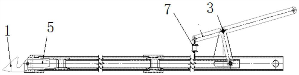
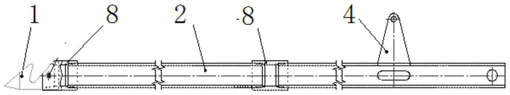
[0026] Such as Figure 1-Figure 4 As shown, an embodiment of the present invention discloses a deep-hole wire pliers, which includes an outer pliers, an inner pliers and a trigger bar 3, wherein,
[0027] The outer pliers include an outer notch 1, an outer tube 2 and a support plate 4, wherein the outer notch 1 is arranged at the head end of the outer tube 2, and the support plate 4 is arranged at the end of the outer tube 2 on the outer wall;
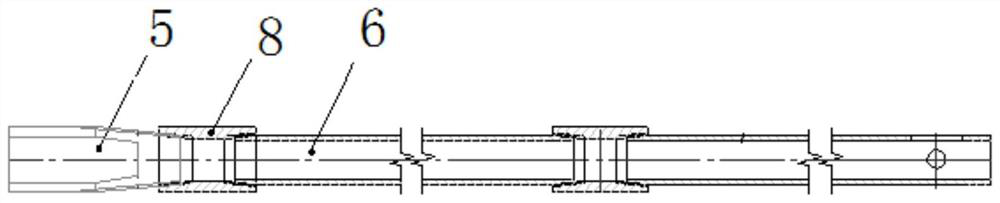
[0028] The inner pliers include an inner notch 5 and an inner tube 6, and the inner notch 5 is connected to the head end of the inner tube;
[0029] The...
PUM
Abstract
The invention relates to a deep hole wire cutter. The deep hole wire cutter comprises an outer cutter, an inner cutter and a pull rod, wherein the outer cutter comprises an outer shear opening, an outer pipe and a supporting plate, the outer shear opening is formed in the head end of the outer pipe, the supporting plate is arranged on the outer wall of the outer pipe, the inner cutter comprises aninner shear opening and an inner pipe, the inner shear opening is connected to the head end of the inner pipe, the inner pipe is inserted into the outer pipe, moreover, the inner shear opening and the outer shear opening are oppositely arranged, the pull rod comprises a first rod and a second rod, the tail end of the second rod is perpendicularly connected to the first rod, the connecting position between the first rod and the second rod is hinged to the supporting plate, the head end of the second rod is hinged to the inner pipe, and the head end of the first rod is connected to the outer pipe through a stretching spring. According to the disclosed deep hole wire cutter, the structure is simple, the length can meet the requirements of the width and the small aperture of a coal column, moreover, the lengthening function is achieved, up-down meshing of a front-end cutter opening is controlled through front-back pulling of a tail handle, a lower meshing opening is provided with barbs (namely, grooves) so that a diamond mesh wire can be accurately hooked, and a to-be-cut-off object can be accurately positioned in a blind area state.
Description
technical field [0001] The present invention relates to the technical field of wire cutters, and more particularly, relates to a deep hole wire cutter. Background technique [0002] At present, in the field of wire cutter technology, due to the limitations of the wire cutter itself, the space used is limited. For example, in Jining No. 3 Coal Mine, when a narrow coal pillar was left along the goaf roadway for reinforcement with expansion-locking anchor cables, it was discovered through drilling holes that there were abandoned anchor nets and shotcrete supports on the side of the goaf, and most diamond-shaped nets It has not yet been damaged. The two-way reinforced anchor cable needs to pass through the diamond-shaped net to better exert its locking force. The existence of the diamond-shaped net makes it difficult for the anchor cable to pass through the front pocket. above the borehole. [0003] Based on this, it is a technical problem to be solved urgently for those skill...
Claims
Application Information
Patent Timeline
Application Date:The date an application was filed.
Publication Date:The date a patent or application was officially published.
First Publication Date:The earliest publication date of a patent with the same application number.
Issue Date:Publication date of the patent grant document.
PCT Entry Date:The Entry date of PCT National Phase.
Estimated Expiry Date:The statutory expiry date of a patent right according to the Patent Law, and it is the longest term of protection that the patent right can achieve without the termination of the patent right due to other reasons(Term extension factor has been taken into account ).
Invalid Date:Actual expiry date is based on effective date or publication date of legal transaction data of invalid patent.