Oil shielding volatilization device

An oil shielding and oil supply pipe technology is applied in the field of metallized film evaporation oil shielding devices, which can solve the problems of shielding oil vapor affecting the effect of the blank area, difficult to control the shielding oil vapor, affecting the quality of the finished film capacitor, etc.

Pending Publication Date: 2018-11-20
郑州华晶新能源科技有限公司
View PDF13 Cites 4 Cited by
  • Summary
  • Abstract
  • Description
  • Claims
  • Application Information

AI Technical Summary

Problems solved by technology

[0003] Shielding oil is a commonly used isolation material at present, but the existing oil shielding volatilization device is difficult to control and provide quantitative and uniform pressure due to multiple factors such as the residual rate of shielding oil volatilization, the residual amount, and the uncontrollable temperature adjustment point after the residue. Shielding oil vapor, the instability of shielding oil vapor will affect the effect of the blank area, and then affect the quality of the finished film capacitor

Method used


Image

  • Oil shielding volatilization device
  • Oil shielding volatilization device
  • Oil shielding volatilization device

Examples


Embodiment 1

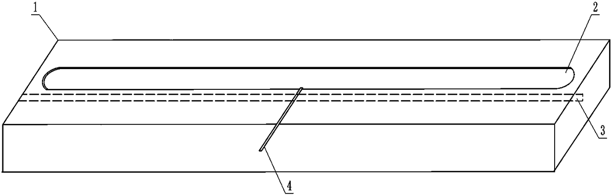
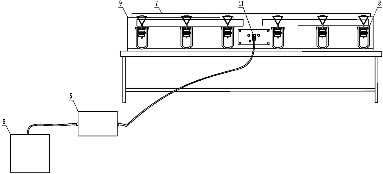
[0024] Such as Figure 1-4 As shown, an oil shielding volatilization device includes a boat-type heating plate 1, an electric heating tube 3, an oil supply pipe 4 and a micro-flow control pump 5, and the upper surface of the boat-type heating plate 1 is provided with a shallow evaporation groove 2, so that The bottom surface of the shallow evaporation tank 2 is a horizontal and straight structure, the electric heating tube 3 is embedded in the boat heating plate 1, the electric heating tube 3 is arranged below the shallow evaporation tank 2, and the supply The oil inlet end 41 of the oil pipe 4 is connected to the oil outlet of the micro-flow control pump 5 , and the oil outlet end of the oil supply pipe 4 is connected to the evaporation shallow tank 2 . The shape of the shallow evaporation groove 2 is specifically a horizontal strip shape, and the shallow evaporation groove 2 includes two sides arranged in parallel and an arc-shaped transition portion connecting the ends of t...

Embodiment 2

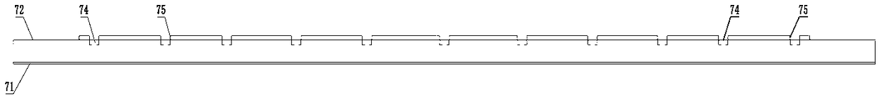
[0030] The difference between this embodiment and Embodiment 1 is that the depth of the evaporation shallow groove 2 is preferably set to 1 mm, and the height of the vertical barrier wall 75 is set to 1 cm.

[0031] After testing, the average thickness of the oil film in the blank area of ​​the shielding oil using the original technology and equipment is 60 nanometers, the deviation range: 60%, and there is a flowing oil film between the film layers. After adopting the oil shielding volatilization device in this embodiment, the average thickness of the oil film in the blank area of ​​the shielding oil is 30 nanometers, and the deviation range is 10%. By comparison, the oil shielding volatilization device in this embodiment has the characteristics of strong consistency and more uniform oil film thickness, which provides convenience for effectively cleaning the oil film during metal vapor deposition, and makes the oil residue of the finished metallized film reach a trace amount, ...


PUM

PropertyMeasurementUnit
depthaaaaaaaaaa
heightaaaaaaaaaa
heightaaaaaaaaaa

Abstract

The invention provides an oil shielding volatilization device. The oil shielding volatilization device comprises a boat type heating plate, an electric heating pipe, an oil supply pipe and a micro flow control pump. The upper surface of the boat type heating plate is provided with an evaporation shallow groove. The bottom surface of the evaporation shallow groove is of a horizontal flat structure.The electric heating pipe is embedded in the boat type heating plate and arranged under the evaporation shallow groove. The oil inlet end of the oil supply pipe is connected with an oil outlet of themicro flow control pump. The oil outlet end of the oil supply pipe communicates with the evaporation shallow groove. The oil shielding volatilization device has the advantages of scientific design, stable oil quantity, uniform oil pressure and good product quality.

Description

technical field [0001] The invention relates to an oil shielding device for vapor deposition of a metallized film, in particular to an oil shielding volatilization device. Background technique [0002] The metallized film used in film capacitors needs to evaporate and deposit metal through a vacuum winding coating machine. Before evaporating and depositing metal, the entire film surface needs to be isolated into a specified width according to the technical specifications of downstream customers' film capacitors, and the isolation band To achieve the specified width, the area where metal needs to be evaporated is called the metal layer, and the isolation zone area is called the blank. At this time, a process and material are needed to coat an isolation layer on the base film in advance to prevent metal deposition, and ensure that the blank area maintains the performance of the original base film, and there is no secondary "contamination" material intervening to avoid Affect ...

Claims


Application Information

Patent Timeline
Patent Type & Authority Applications(China)
IPC IPC(8): C23C14/04
CPCC23C14/04
Inventor 王军友陈鸿杰杨晓磊
Owner 郑州华晶新能源科技有限公司
Why Eureka
Try Eureka