A kind of optical fiber device testing equipment

A technology of optical fiber devices and testing equipment, which is applied in the fields of communication and optical fiber device detection, and can solve problems such as low efficiency and accuracy, low production efficiency, and high product defective rate

Active Publication Date: 2020-04-21
SHANDONG JIANBO TELECOMM EQUIP
View PDF12 Cites 0 Cited by
  • Summary
  • Abstract
  • Description
  • Claims
  • Application Information

AI Technical Summary

Problems solved by technology

The existing equipment detects fewer items and requires manual loading and unloading
[0003] The shortcomings of the existing equipment are: 1. A set of equipment can only detect a certain performance parameter, and cannot realize automatic multi-functional detection; 2. The disassembly and assembly of the end protection cover needs to be completed manually, and the production efficiency is low ;3. The end of the optical fiber core is directly tested without polishing and optimization, and the product performance is not improved; 4. Due to the flexibility of the optical fiber, most of them are handled manually, and the efficiency and accuracy are not high; 5. The pins are in the process of processing It is easy to be deformed, and the defective rate of the product is high

Method used


Image

  • A kind of optical fiber device testing equipment
  • A kind of optical fiber device testing equipment
  • A kind of optical fiber device testing equipment

Examples


Embodiment Construction

[0043] The present invention will be further described below in conjunction with the accompanying drawings and embodiments.

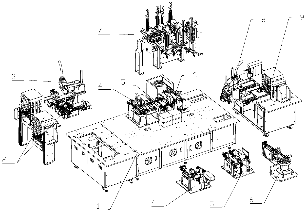
[0044] like figure 1 As shown, an optical fiber device testing equipment includes a frame 1 and a feeding device 2 installed on it, a feeding manipulator device 3, a pre-test carding module 4, an optical fiber device performance testing module 5, and a protective cover device 6. Stepping and handling device 7, folding and placing manipulator device 8 and unloading device 9.

[0045] The feeding device 2 is connected with the carding module 4 before detection through the feeding manipulator device 3 . The pre-test carding module 4, the optical fiber device performance test module 5 and the protective cover installation device 6 are sequentially connected. The position of the stepping and conveying device 7 corresponds to the carding module 4 before detection, the optical fiber device performance detection module 5 and the protective cover installation ...


PUM


Abstract

The invention relates to the technical field of the communication. Optical fiber device detection equipment comprises a rack and a feeding device, a feeding manipulator device, a before-detection analysis module, an optical fiber device performance detection module, a protective cap mounting device, a stepping conveying device, a foldable manipulator placing device and a blanking device which arearranged on the rack; the feeding device is joined with the before-detection analysis module through the feeding manipulator device; the before-detection analysis module, the optical fiber device performance detection module and the protective cap mounting device are orderly joined; the location of the stepping conveying device is corresponding to the before-detection analysis module, the opticalfiber device performance detection module and the protective cap mounting device; and the protective cap mounting device is joined with the blanking device through the foldable manipulator placing device. The optical fiber device detection equipment has the advantages of being high in automation degree, high in working efficiency, high in finished product yield and extensive in testing range.

Description

technical field [0001] The invention relates to the technical field of communication, in particular to the field of optical fiber device detection. Background technique [0002] Optical fiber communication test refers to the test work to verify the characteristics of optical fiber communication system. There are many items to be carried out, including the full attenuation of optical fiber line, the output optical power of optical transmitter, the sensitivity of optical receiver, dynamic range, signal jitter, and light transmission ability test Wait. The existing equipment detects fewer items and requires manual loading and unloading. [0003] The shortcomings of the existing equipment are: 1. A set of equipment can only detect a certain performance parameter, and cannot realize automatic multi-functional detection; 2. The disassembly and assembly of the end protection cover needs to be completed manually, and the production efficiency is low ;3. The end of the optical fibe...

Claims


Application Information

Patent Timeline
Patent Type & Authority Patents(China)
IPC IPC(8): G01M11/00G01B21/30
CPCG01B21/30G01M11/30
Inventor 吴美珍
Owner SHANDONG JIANBO TELECOMM EQUIP
Why Eureka
Try Eureka