A low-turbulence compact circulating water tunnel experimental device

A technology of low turbulence and experimental equipment, applied in the field of hydrodynamic experimental research, can solve the problems of reducing the applicability of water tunnel experimental equipment, high construction costs of vertical water tunnels, and increasing the occupied space of water tunnels, achieving compact structure , Occupy small space, eliminate the effect of large-scale vortex

Active Publication Date: 2020-08-18
XI AN JIAOTONG UNIV
View PDF7 Cites 2 Cited by
  • Summary
  • Abstract
  • Description
  • Claims
  • Application Information

AI Technical Summary

Problems solved by technology

Due to the high construction cost and large space occupation of vertical water tunnels, and the fact that the flow velocity in the experimental section changes with the water level, most existing water tunnels adopt a circular design
[0003] The advantages of the circulating water tunnel are high flow rate and large flow rate, but it is driven by power equipment, and it is difficult to eliminate the interference to the flow. Usually, the quality of the flow field in the experimental section is low
Existing circulating water tunnels often reduce water flow disturbance by designing complex rectification devices at the inlet or extending the outlet pipes of power equipment, which not only increases the occupied space of the water tunnel, but also dramatically increases the manufacturing cost. Reduced applicability of water tunnel experiment setup

Method used


Image

  • A low-turbulence compact circulating water tunnel experimental device
  • A low-turbulence compact circulating water tunnel experimental device
  • A low-turbulence compact circulating water tunnel experimental device

Examples


Embodiment Construction

[0030] The present invention will be further described below in conjunction with accompanying drawing and specific embodiment:

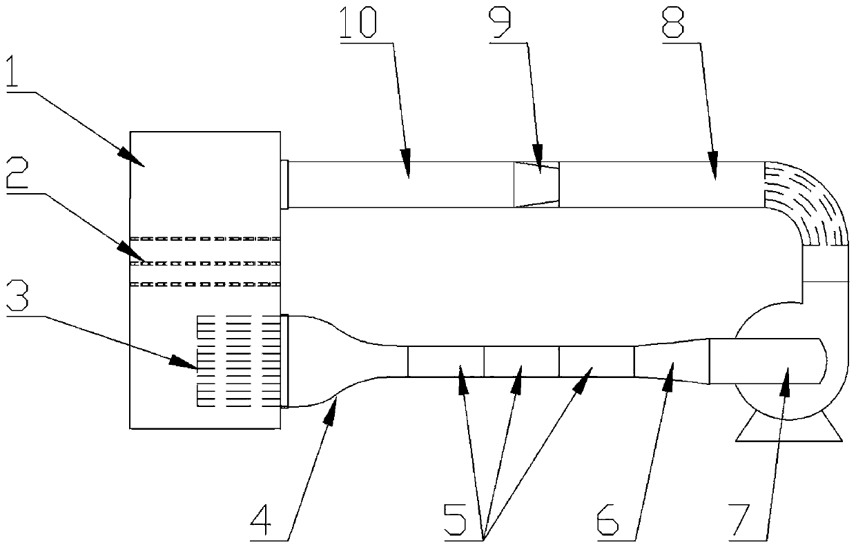
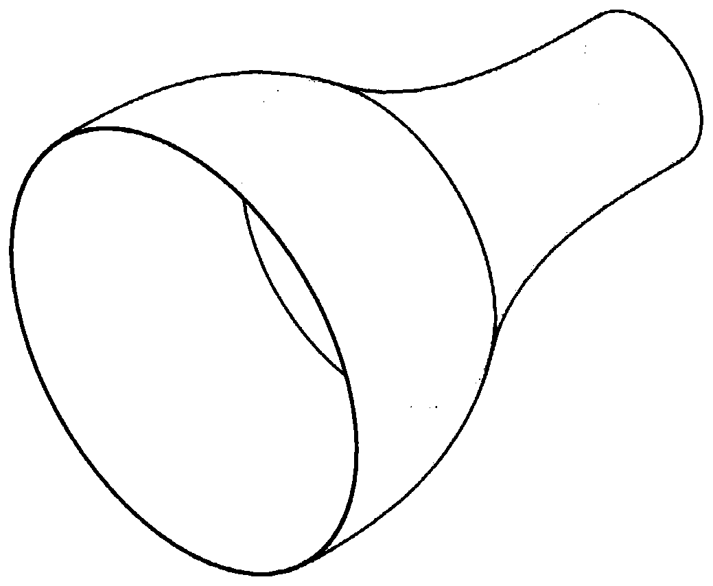
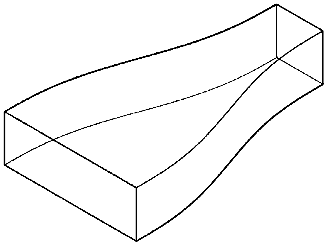
[0031] see Figure 1 to Figure 3 , the present invention provides a low-turbulence compact circulating water tunnel experimental device, including a water tank 1, a perforated plate 2, a rectifying grid 3, a contraction section 4, an experiment section 5, an expansion section 6, a centrifugal pump 7, a return section 8, a circular Change square section 9 and gradually expand section 10.

[0032] see figure 1 , the size of the water tank 1 is 1m*1m*2m, there are water inlet and outlet on the same side, the water inlet is rectangular 0.9m*0.3m, located at the top, the water outlet is circular r=0.3m, located at the bottom, same Side openings minimize pipe laying lengths and bends. There are 3 layers of perforated plates in the water tank. The thickness of the perforated plates is 5mm, and the punching hole diameter is 20mm. The 3 layers of perforate...


PUM


Abstract

The invention discloses a low-turbulence compact circulating water tunnel experimental device, comprising a water tank (1), a centrifugal pump (7), and a porous plate (2) and a honeycomb screen (3) which are disposed in the water tank (1). The water tank (1) has a water inlet at the upper part and a water outlet at the lower part at the same side. The porous plate (2) is installed between the water inlet and the water outlet. The honeycomb screen (3) is installed at the water outlet, and has an outlet successively connected a contraction section (4), an experimental section (5) and an expansion section (6). The outlet of the expansion section (6) is connected to the inlet of the centrifugal pump (7). The outlet of the centrifugal pump (7) is successively connected with a backflow section(8), a round-to-square section (9) and a diverging section (10). The outlet of the diverging section (10) is connected to the water inlet of the water tank (1). The hydrodynamic design used by the invention greatly reduces the turbulence of a flow field in the experimental section. The whole experimental device has a compact structure, a small occupied space and low manufacturing cost, which greatly improves the applicability of the water tunnel experimental device.

Description

technical field [0001] The invention belongs to the field of hydrodynamic experiment research, in particular to a low-turbulence compact circulating water tunnel experimental device. Background technique [0002] In the field of research related to hydrodynamics, a water tunnel experimental device with good performance is the key equipment to obtain important flow laws and experimental results. There are two main structural forms of the water tunnel: one is the vertical water tunnel, the water flows from the steady flow section through the contraction section by gravity, and flows into the experimental section at a certain speed, also known as the gravity water tunnel; the other is the circulating water tunnel. The water flow is driven by the power equipment to flow through the stable section, the contraction section, the experimental section and other structures in turn, and through the return pipe to form a cycle. Due to the high construction cost and large space occupati...

Claims


Application Information

Patent Timeline
Patent Type & Authority Patents(China)
IPC IPC(8): G01M10/00
CPCG01M10/00
Inventor 张荻朱发挥谢永慧姜伟
Owner XI AN JIAOTONG UNIV
Why Eureka
Try Eureka