Laser scanning packaging system and method

A laser scanning and encapsulation system technology, which is applied in glass molding, glass manufacturing equipment, electrical components, etc., can solve the problems of uneven energy distribution and poor applicability in the encapsulation area, so as to improve the uniformity of energy distribution and the applicability of the process , Improve the effect of air tightness

Active Publication Date: 2019-03-05
SHANGHAI MICRO ELECTRONICS EQUIP (GRP) CO LTD
View PDF6 Cites 0 Cited by
  • Summary
  • Abstract
  • Description
  • Claims
  • Application Information

AI Technical Summary

Problems solved by technology

[0004] The purpose of the present invention is to provide a laser scanning packaging system and method to solve the problems of uneven energy distribution and poor applicability in the packaging area existing in the prior art. The purpose of matching the packaging area and the uniform energy distribution of the packaging area improves the process applicability of laser scanning glass packaging

Method used


Image

  • Laser scanning packaging system and method
  • Laser scanning packaging system and method
  • Laser scanning packaging system and method

Examples


Embodiment 1

[0095] In Embodiment 1, the glass encapsulation method is used to encapsulate an annular encapsulation area, the modulated light spot moves at a uniform speed along the extension direction of the encapsulation area for scanning, and the glass frit is sintered for encapsulation.

[0096] The shape of the modulated light spot can be adjusted to a circular light spot or a fan-shaped light spot as required.

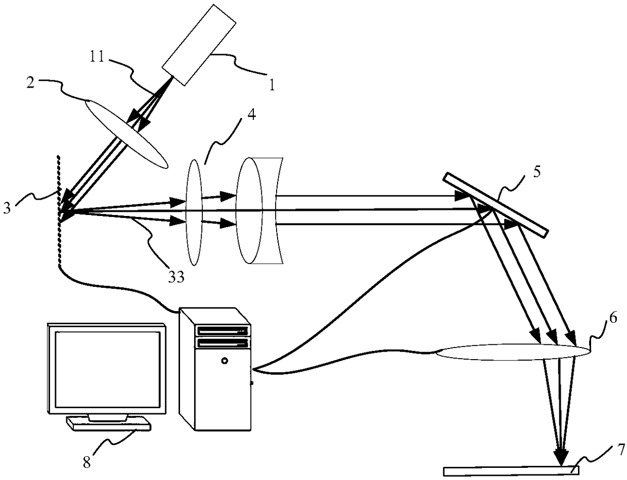
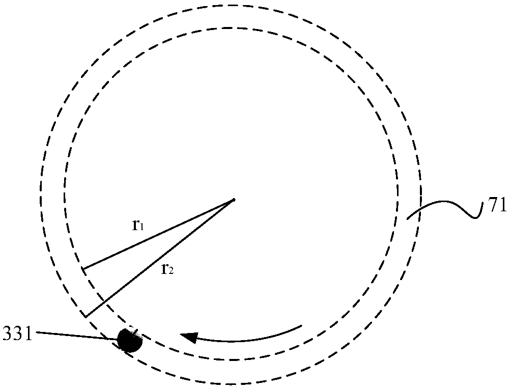
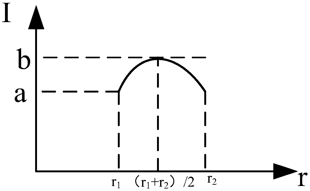
[0097] see figure 2 and image 3 , when the spot shape is a circular spot 331, the energy in the circular spot 331 is given by r 1 to r 2 Gradually increasing, when the circular spot 331 scans at a constant speed along the extending direction of the annular packaging area 71, it is required that in the annular packaging area 71, the energy in the annular packaging area 71 is evenly distributed, that is, in the radial direction in the annular packaging area 71, by r 1 to r 2 The energy of the annular encapsulation area 71 in the area is evenly distributed, therefore, the...

Embodiment 2

[0102] see Figure 6 , in this embodiment, the laser scanning glass packaging method is used to package a rectangular packaging area 72, the rectangular packaging area includes several linear packaging areas and several round corner packaging areas, the linear packaging area and the described Round corner package areas are connected alternately, see Figure 6 and Figure 7 , in the rectangular packaging area 72, taking one of the round corner packaging areas as an example, the two linear packaging areas connected to the two ends of the round corner packaging area 723 are defined as the first linear packaging area 721 and the second linear packaging area 721. Packaging area 722, the first linear packaging area 721 domain includes a first packaging area 721a and a second packaging area 721b, and the second linear area 722 includes a third packaging area 722a and a fourth packaging area 722b, The first encapsulation area 721a, the second encapsulation area 721b, the round corne...

Embodiment 3

[0122] This embodiment is used to package a rectangular package area, and the shape of the modulated light spot is a circular light spot 331 and / or a rectangular light spot 332. In the first package area 721a, the second package area 721b, the circle In the corner encapsulation area 723 , the third encapsulation area 722 a and the fourth encapsulation area 722 b , when the modulated light spot moves to the boundary of two adjacent areas, the shape of the modulated light spot is transformed.

[0123] see Figure 13 , Figure 13 The first packaging method provided for the third embodiment, the modulated light spot in the first packaging area 721a, the round corner packaging area 723 and the fourth packaging area 722b is a circular light spot 331, and in the second packaging area 721b and the modulation spot in the third encapsulation region 722a is a rectangular spot 332; please refer to Figure 14 , Figure 14 The second packaging method provided for the third embodiment, the ...


PUM

PropertyMeasurementUnit
sizeaaaaaaaaaa

Abstract

The invention provides a laser scanning packaging system and a method. The system comprises a light source module for providing incidence laser, a micro-reflecting mirror array and a control module, wherein the control module is used for carrying out light spot modulation on the incidence laser through adjusting the micro-reflecting mirror array, and the light spot modulation comprises the step ofcarrying out light spot morphology modulation and light spot energy distribution modulation on the incidence laser. Therefore, light spot morphology modulation and light spot energy distribution modulation can be carried out in real time according to the morphology and size of an area required to be packaged, thus, the aim that the morphology of a light spot is matched with the packaged area andthe energy of the packaged area is uniformly distributed is achieved, and the adaptability of a laser-scanning glass packaging process is improved; and a reflecting direction of a modulated light spotis adjusted through arranging a reflecting mirror group, and then, the aim of scanning the packaged area by the laser is achieved, so that mechanical vibrations are reduced, and the gas tightness oflaser-scanning glass packaging is improved.

Description

technical field [0001] The invention belongs to the field of display manufacturing, and relates to a laser scanning packaging system and method. Background technique [0002] In the field of display manufacturing, especially in the manufacturing process of organic light-emitting displays (OLEDs), laser scanning glass packaging is usually used, specifically, the pre-sintered glass frit (FRIT) is used as the intermediate packaging solder, and the glass frit is melted by laser irradiation. Bonding between two glass substrates to realize laser scanning glass packaging. [0003] In the prior art, the glass substrate is usually packaged with a spot with a single shape or a single energy distribution. The lack of spot shape and spot energy distribution modulation may cause large beam energy dispersion and weak exposure energy per unit area. It is beneficial to the packaging of the substrate and reduces the technological level of laser scanning glass packaging; especially when pack...

Claims


Application Information

Patent Timeline
Patent Type & Authority Applications(China)
IPC IPC(8): C03B23/203H01L51/56
CPCC03B23/203H10K71/00
Inventor 李水艳朱锋
Owner SHANGHAI MICRO ELECTRONICS EQUIP (GRP) CO LTD
Why Eureka
Try Eureka