
Geological structure physical simulation experiment device for ultra-high gravity field of large-scale centrifugal machine
A technology of supergravity field and geological structure, applied in the direction of educational appliances, teaching models, instruments, etc., can solve the problems of small space in the drum centrifuge cabin, small model modeling size, and large changes in radial acceleration of gravity, etc., to achieve The effect of accurate physical simulation of geological structure, effective space saving and elimination of simulation error
- Summary
- Abstract
- Description
- Claims
- Application Information
AI Technical Summary
Problems solved by technology
Method used
Image

Examples
Embodiment Construction
[0027] The present invention will be described in further detail below in conjunction with the accompanying drawings and specific embodiments.
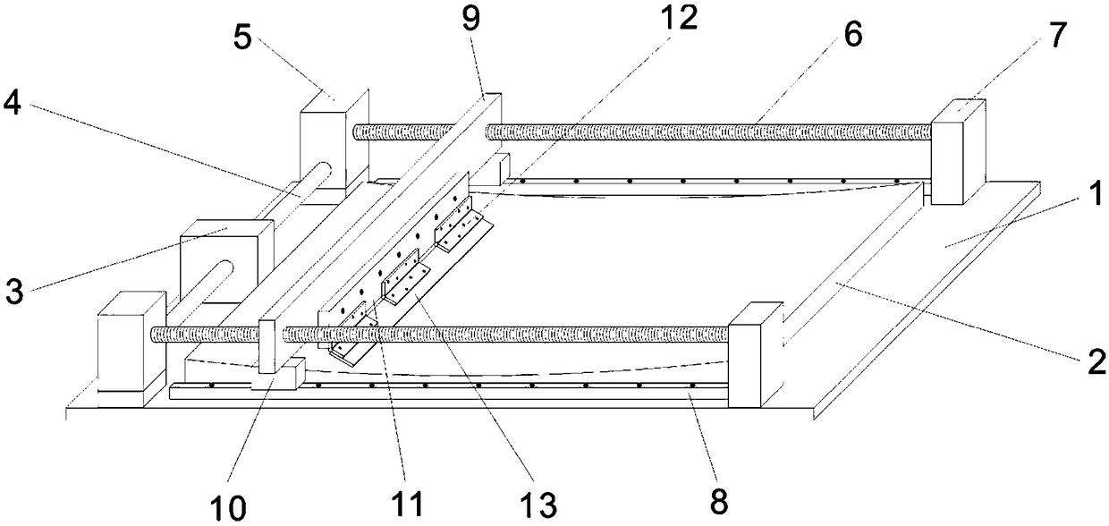
[0028] Such as figure 1 As shown, the present invention includes a bottom plate 1, a curved table 2, a power part and a baffle part.
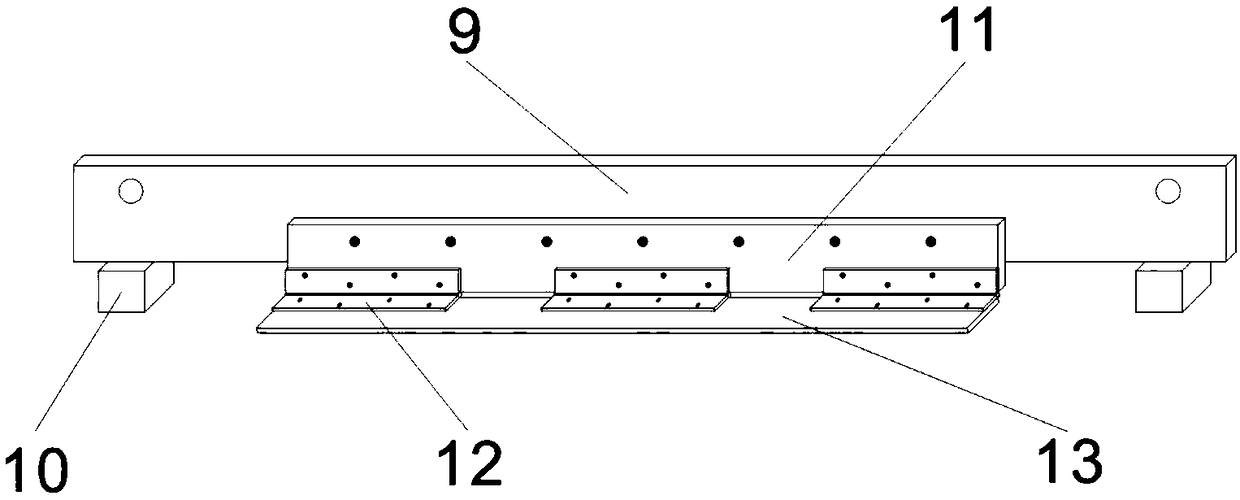
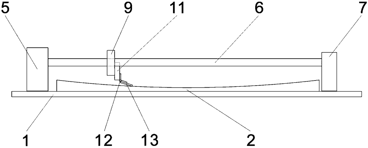
[0029] Such as figure 1 As shown, the bottom plate 1 is placed on the hanging basket of the centrifuge, and screw assemblies are installed on both sides of the bottom plate 1. The screw assembly includes a screw 6, a sliding guide rail 8, a steering gear 5 and a screw support column 7, and the screw 6 is arranged parallel to the base plate 1, and the two ends of the screw rod 6 are respectively supported and connected between the diverter 5 and the screw rod support column 7, and the diverter 5 and the screw rod support column 7 are fixed on the base plate 1, and the base plate below the screw rod 6 1 are fixed with sliding guide rails 8; the bottom plate 1 between the same ends of the two screw rods...
PUM
 Abstract
Description
Claims
Application Information