Target object recognition method and device and operation equipment

A technology for target objects and operating equipment, applied in the field of unmanned aerial vehicles, can solve problems such as poor safety of operating equipment, and achieve the effect of improving reliability, stability and safety

Active Publication Date: 2019-04-16
GUANGZHOU XAIRCRAFT TECH CO LTD
View PDF26 Cites 4 Cited by
  • Summary
  • Abstract
  • Description
  • Claims
  • Application Information

AI Technical Summary

Problems solved by technology

[0004] Embodiments of the present invention provide a target object recognition method and device, and operating equipment to at least solve the technical problem in the related art that the target object in the traveling direction of the operating equipment cannot be avoided, resulting in poor safety of the operating equipment

Method used


Image

  • Target object recognition method and device and operation equipment
  • Target object recognition method and device and operation equipment
  • Target object recognition method and device and operation equipment

Examples


Embodiment 1

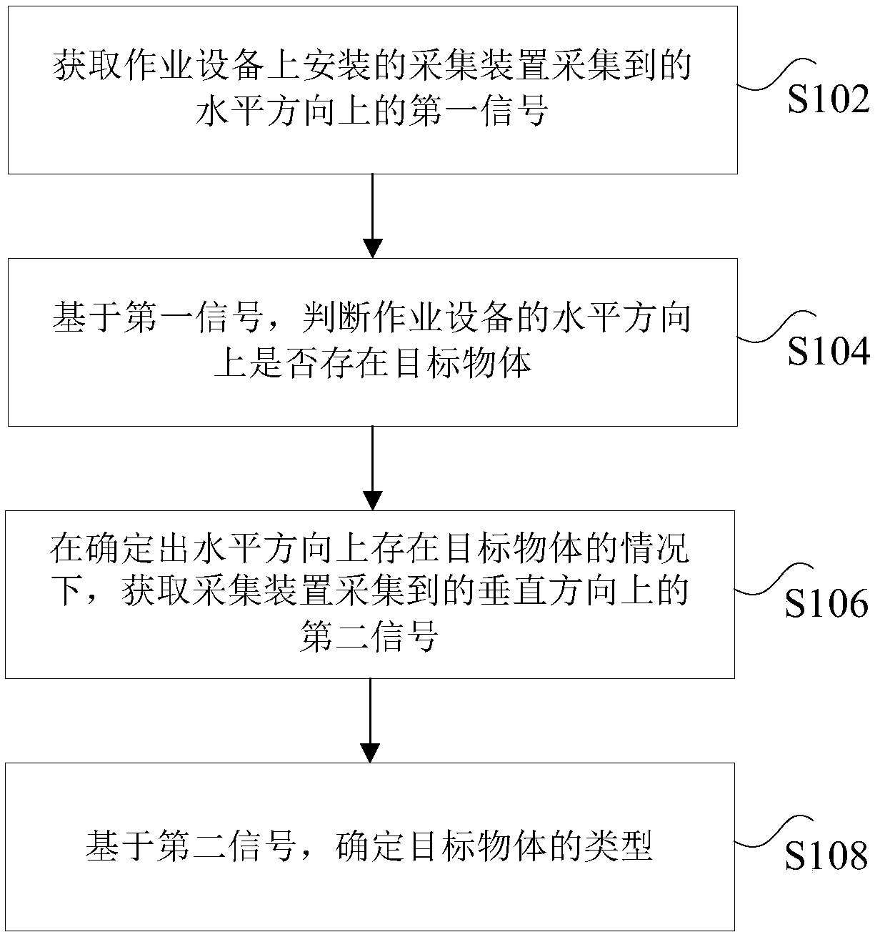
[0035] According to an embodiment of the present invention, an embodiment of a method for identifying a target object is provided. It should be noted that the steps shown in the flowcharts of the accompanying drawings can be executed in a computer system such as a set of computer-executable instructions, and , although a logical order is shown in the flowcharts, in some cases the steps shown or described may be performed in an order different from that shown or described herein.

[0036] figure 1 is a flow chart of a target object recognition method according to an embodiment of the present invention, such as figure 1 As shown, the method includes the following steps:

[0037] Step S102, acquiring the first signal in the horizontal direction collected by the collection device installed on the operation equipment.

[0038] Specifically, the above-mentioned operating equipment may be a plant protection unmanned aerial vehicle, and acquisition devices are installed on the horiz...

Embodiment 2

[0077] According to an embodiment of the present invention, an embodiment of an identification device for a target object is provided.

[0078] Figure 8 is a schematic diagram of an identification device for a target object according to an embodiment of the present invention, such as Figure 8 As shown, the device includes:

[0079] The first acquisition module 82 is configured to acquire the first signal in the horizontal direction collected by the acquisition device installed on the operation equipment.

[0080] Specifically, the above-mentioned operating equipment may be a plant protection unmanned aerial vehicle, and acquisition devices are installed on the horizontal and vertical directions of the unmanned aerial vehicle body, which can collect signals used to characterize the environmental information of the surrounding environment of no one. The acquisition device may be Laser radar, infrared, vision-based devices or millimeter-wave radar, the present invention does ...

Embodiment 3

[0091] According to an embodiment of the present invention, an embodiment of working equipment is provided.

[0092] Figure 9 is a schematic diagram of a working device according to an embodiment of the present invention, such as Figure 9 As shown, the operating equipment includes:

[0093] The collecting device 92 is used for collecting the first signal in the horizontal direction and the second signal in the vertical direction.

[0094] Specifically, the above-mentioned operating equipment may be a plant protection unmanned aerial vehicle, and acquisition devices are installed on the horizontal and vertical directions of the unmanned aerial vehicle body, which can collect signals used to characterize the environmental information of the surrounding environment of no one. The acquisition device may be Laser radar, infrared, vision-based devices or millimeter-wave radar, the present invention does not specifically limit this, as long as the environmental information of the...


PUM


Abstract

The invention discloses a target object recognition method and device and operation equipment. The method comprises the following steps of acquiring a first signal in a horizontal direction collectedby an acquisition device installed on the operation equipment; judging whether a target object exists in the horizontal direction of the operation equipment based on the first signal; when it is determined that the target object exists in the horizontal direction, acquiring a second signal in a vertical direction acquired by the acquisition device; and based on the second signal, determining the type of the target object. According to the target object recognition method and device and operation equipment, the technical problem that the target object in the advancing direction of the operatingequipment cannot be recognized in the related technology, so that the safety of the operating equipment is poor is solved.

Description

technical field [0001] The present invention relates to the field of unmanned aerial vehicles, in particular, to a method and device for identifying a target object, and operating equipment. Background technique [0002] Plant protection drones provide plant protection operations for crop growth. Compared with drones such as aerial photography or surveying and mapping, their working environment is complex. Especially when providing pesticide spraying for crops, drones need to fly on the surface of plants. Generally, it is 1-3 meters. The farmland environment is complex, the surrounding windbreaks and other blocking GPS signals are weak, or there are many obstacles such as trees and utility poles, which will affect the plant protection operations of the aircraft. The existing UAV flight plan is generally to take off at the take-off point, go to the operation area to operate, and return to the flight after the operation is completed, ignoring the impact of the operating enviro...

Claims


Application Information

Patent Timeline
Patent Type & Authority Applications(China)
IPC IPC(8): G01S13/04G01S13/02
CPCG01S13/02G01S13/04
Inventor 陈有生
Owner GUANGZHOU XAIRCRAFT TECH CO LTD
Why Eureka
Try Eureka