Building method for case-in-place floor

An on-site pouring and floor slab technology, which is applied to the preparation of building components on site, floor slabs, construction, etc., can solve the problems affecting the flatness of the floor slab, the change of the thickness of the protective layer, and the quality of the floor slab, so as to save labor costs and reduce subsequent processes , Improve the effect of pouring quality

Active Publication Date: 2019-04-19
广州市黄埔建筑工程总公司
View PDF6 Cites 4 Cited by
  • Summary
  • Abstract
  • Description
  • Claims
  • Application Information

AI Technical Summary

Problems solved by technology

However, during the operation process, workers will step on the concrete, and there will be gravure marks after stepping on it, which will change the thickness of the protective layer, affect the quality of the floor, and also affect the flatness of the floor, although leveling can be done later layer, but it increases the process, which is time-consuming and labor-intensive

Method used


Image

  • Building method for case-in-place floor
  • Building method for case-in-place floor
  • Building method for case-in-place floor

Examples


Embodiment Construction

[0050] The present invention will be described in further detail below in conjunction with the accompanying drawings.

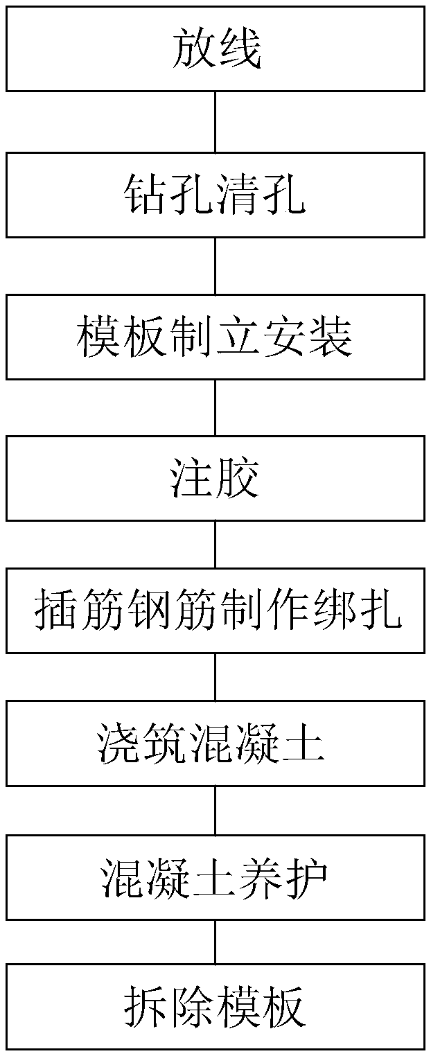
[0051] A construction method for cast-in-place slabs, cf. figure 1 , including the following steps:

[0052] Sp1: Set off the thread, according to the size data, use the ink fountain to bounce the thread on the wall;

[0053] Sp2: Drill and clean the hole, use an electric drill to make a hole on the wall, and then use a hair dryer to blow off the dust in the hole;

[0054] Sp3: Formwork erection and installation, set up a shelf, and install the floor formwork on the shelf;

[0055] Sp4: Glue injection, inject glue into the hole;

[0056] Sp5: Inserting steel bars to make binding, inserting steel bars into the holes, and binding the external steel bars to fix the external steel bars;

[0057] Sp6: Pouring concrete, pouring concrete on formwork, covering steel bars, and troweling;

[0058] Sp7: Concrete curing, watering and curing several times a day for a...


PUM


Abstract

The invention relates to a building method for a case-in-place floor, and relates to the technical field of the building construction. The method comprises the following steps: Sp1: paying off; Sp2: drilling and hole-cleaning; Sp3: erecting and installing a template; Sp4: injecting glue; Sp5: manufacturing and bundling a reinforced steel bar; Sp6: pouring concrete; Sp7: curing the concrete; and Sp8: detaching the template, wherein a troweling device is used in troweling operation in the Sp6. The troweling device comprises a support rod supported on a wall surface, a moving frame slidably installed on the support rod, a driving component installed on the moving frame, an installing frame slidably installed on the lower surface of the moving frame, a power component installed on the installing frame, a clamping component installed on the installing frame, and a troweling machine connected with the clamping component. The method is capable of, through controlling the driving component andthe power component, controlling operation of the troweling machine, avoiding a person from stepping on concrete, reducing a situation that a thickness of a protecting layer is not enough, improvingflatness of the floor, and improving quality of the floor.

Description

technical field [0001] The invention relates to the technical field of building construction, in particular to a building method for pouring floor slabs on site. Background technique [0002] At present, in the field of building construction, when pouring floor concrete, according to the requirements of quality control standards and acceptance specifications, the thickness of the protective layer of main stressed steel bars on the floor is 15mm, and the allowable error is +8mm~-5mm. In other words, the protective layer of steel bars The thickness should be controlled within the range of 23mm to 10mm. The commonly used control method in construction is: first pop up the floor concrete elevation control line, then pour and vibrate the concrete, and finally smooth it. [0003] During the smoothing process, the general worker will use a trowel to smooth the concrete. However, during the operation process, workers will step on the concrete, and there will be gravure marks after...

Claims


Application Information

Patent Timeline
Patent Type & Authority Applications(China)
IPC IPC(8): E04B5/32E04G11/36
CPCE04B5/32E04G11/36
Inventor 欧阳东肖斯娜张进陆远宁何彦田俊泽陆烨壕方筱栋
Owner 广州市黄埔建筑工程总公司
Why Eureka
Try Eureka