Heat pipe type double-cone vacuum drier

A vacuum dryer and vacuum drying technology, applied in the direction of non-progressive dryers, dryers, drying solid materials, etc., can solve the problems of double cone vacuum dryer paralysis, scrapping, easily exposed welding quality problems, heat transfer medium leakage, etc. problem, to achieve the effect of optimizing the drying effect, improving the drying efficiency, and increasing the heat dissipation area

Inactive Publication Date: 2019-05-07
MENGZHOU YUANHONG DRYING EQUIP RES & DEV CO LTD
View PDF1 Cites 0 Cited by
  • Summary
  • Abstract
  • Description
  • Claims
  • Application Information

AI Technical Summary

Problems solved by technology

The two ends of the heat dissipation pipe of the double-cone vacuum drying chamber and the inner cavity between the outer shell and the inner shell are the reasons for the penetration and ventilation. The two ends of the heat dissipation pipe and the outer shell must be welded, fixed and sealed as one. Hundreds of heat pipes, one heat pipe has two ends, it is difficult to meet the welding processing index requirements of the welding connection between the two ends of hundreds of heat pipes and the inner shell shell, but it is still easy to expose the welding Quality problems, as long as there is a little welding quality problem in the welding points between the two ends of hundreds of heat pipes and the inner shell shell, the leaking welding points will cause the leakage of the heat transfer medium, and the leakage repair is also very troublesome, eventually leading to the entire three-dimensional heating The type double cone vacuum dryer is paralyzed and scrapped and cannot be used

Method used


Image

  • Heat pipe type double-cone vacuum drier
  • Heat pipe type double-cone vacuum drier
  • Heat pipe type double-cone vacuum drier

Examples


Embodiment

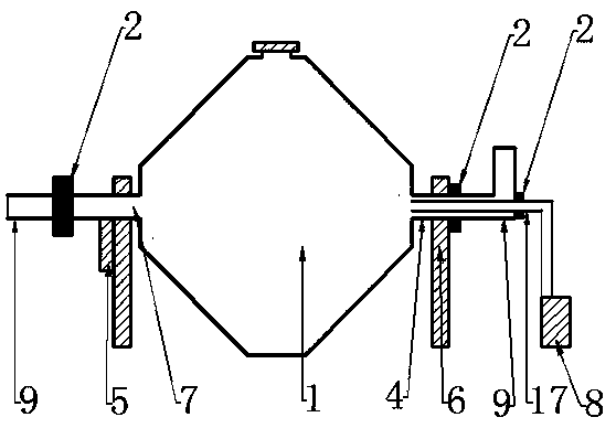
[0063] Such as figure 1 A heat pipe type double-cone vacuum dryer shown includes a double-cone vacuum drying chamber 1, a support wheel bracket 6, a rotary joint 2, a vacuum unit 8, a driving device 5, an air guide pipe 17, a heat conduction pipe 9, and a discharge valve 10.

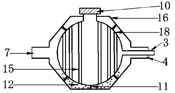
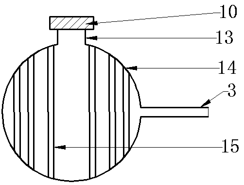
[0064] The double-cone vacuum drying chamber 1 includes a heating chamber 16, a drying chamber 18, and a support 11.

[0065] The heating chamber 16 of the double-cone vacuum drying chamber 1 has a heat energy inlet 7 and a heat energy outlet 4 .

[0066] Described support roller support 6 comprises support roller, support.

[0067] 1. The supporting wheel is fixed on the bracket.

[0068] The heat energy inlet 7 and the heat energy outlet 4 of the heating chamber 16 of the double-cone vacuum drying chamber 1 are supported by the supporting rollers of the supporting roller bracket 6 .

[0069] The driving device 5 is installed on the bracket of the supporting wheel bracket 6, and the driving device 5 ...


PUM


Abstract

The invention discloses a heat pipe type double-cone vacuum drier. The drier comprises a double-cone vacuum drying bin, a supporting wheel support, a rotating joint, a vacuum unit, a driving device, an air guide pipe, a heat conduction pipe and a discharging valve. The double-cone vacuum drying bin comprises a heating bin, a drying bin and a support. A heat energy inlet and a heat energy outlet ofthe heating bin of the double-cone vacuum drying bin are supported and borne by supporting wheels of the supporting wheel support, the driving device drives the double-cone vacuum drying bin to rotate. The drying bin is arranged inside the heating bin, connecting of the heating bin and the drying bin is supported and fixed by the support, the drying bin comprises a bin body, a heat pipe type radiating pipe, an exhaust pipe and a material feeding and discharging port. The discharging valve is fixedly installed on the material feeding and discharging port of the drying bin. According to the drier, the heat dissipation area of the bin body of the drying bin and the heat pipe type radiating pipe is increased by 10-60 times when the drying bin is same in volume, the heating and heat conductionspeed of heat energy is increased, the drying efficiency of materials is improved, and the purpose of rapidly drying the materials is achieved; and when one certain heat pipe type radiating pipe is damaged, leakage is generated, the use of the whole heat pipe type double-cone vacuum drier is not influenced.

Description

technical field [0001] The invention relates to a double cone vacuum dryer, in particular to a heat pipe type double cone vacuum dryer. Background technique [0002] The double-cone vacuum dryers currently on the market use the inner wall of the interlayer as a single-layer plane for heat dissipation and heating. The heat dissipation area is small, the material contacting the hot surface is smaller, and the heat energy use efficiency is low. Wet materials often form agglomerates under vacuum, which causes uneven drying of wet materials and affects the drying quality of materials. [0003] Heat pipe technology is a heat transfer element called "heat pipe" invented by G.M.Grover of Los Alamos National Laboratory in the United States in 1963. It makes full use of the principle of heat conduction and the rapid heat transfer properties of refrigeration media. "Phase change" quickly transfers the heat of the heating object to the heat source, and its thermal conductivity exceeds ...

Claims


Application Information

Patent Timeline
Patent Type & Authority Applications(China)
IPC IPC(8): F26B11/06F26B23/10F26B25/04F26B25/00
Inventor 程长青
Owner MENGZHOU YUANHONG DRYING EQUIP RES & DEV CO LTD
Why Eureka
Try Eureka