Solar thermal collector

A technology of solar heat collectors and heat-absorbing fins, which is applied in the field of solar heat collectors, can solve the problems of low utilization rate of solar energy, and achieve the effects of increasing heat collection, increasing heat collection, and increasing heat collection area

Inactive Publication Date: 2019-05-14
湖北安联药业有限公司
View PDF0 Cites 0 Cited by
  • Summary
  • Abstract
  • Description
  • Claims
  • Application Information

AI Technical Summary

Problems solved by technology

[0003] The purpose of the present invention is to provide a solar collector with a novel structure in order to solve the low utilization rate of solar energy of the prior art solar collector.

Method used


Image

  • Solar thermal collector
  • Solar thermal collector

Examples


Embodiment Construction

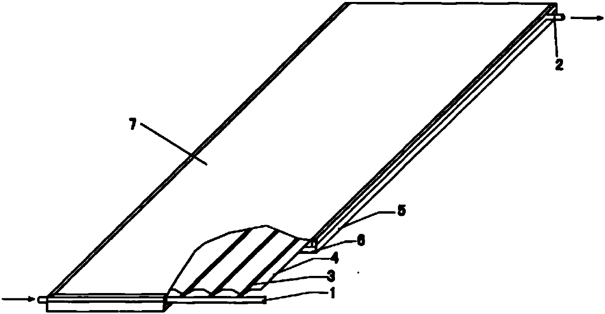
[0011] see figure 1 , figure 2 , the solar heat collector of the present invention comprises a water inlet main pipe 1, a water outlet main pipe 2, a plurality of heat transfer copper pipes 3 connected between the water inlet main pipe and the water outlet main pipe, heat-absorbing fins connected on the heat transfer copper pipes 4, and frame 5, insulation layer 6, glass cover plate 7.

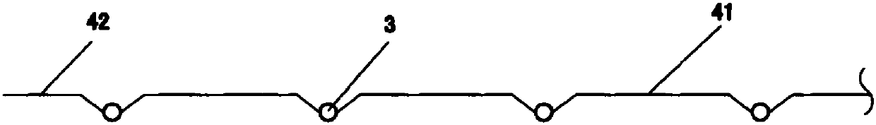
[0012] Cooperate see figure 2 , the heat-absorbing fin 4 in the present invention is a terrace-shaped heat-absorbing fin, and the terrace-shaped heat-absorbing fin is formed by pressing two aluminum alloy plates arranged on the upper and lower sides of the heat transfer copper tube through a special mold. The heat-absorbing fins wrap the heat-transfer copper tubes 3 inside, and form a terraced structure 41 between two adjacent copper tubes, and form a terraced structure 42 outside the edge copper tubes. The upper and lower sides are coated with a heat absorbing coating (not shown). Where...


PUM


Abstract

The invention provides a solar thermal collector, comprising a water inlet main pipe, a water outlet main pipe, a plurality of heat transferring copper pipes connected between the water inlet main pipe and the water outlet main pipe and heat absorption fins connected with the heat transferring copper pipes; wherein the heat absorption fins are ladder-shaped heat absorption fins, the ladder-shapedheat absorption fins are formed by pressing two aluminum alloy plates arranged on the upper side and the lower side of the heat transferring copper pipes through a special mold, the formed heat absorption fins covers the heat transferring copper pipes; ladder-shaped structures are formed between two adjacent copper pipes and the outer side of the edge copper pipe, and a layer of heat absorption coating is respectively coated on the upper side and the lower side of the ladder-shaped heat absorption fins. The solar thermal collector provided by the invention achieves the purposes of improving heat collection power and effectively increasing heat collection area and heat collection capacity. Under the same external dimensions and sunshine conditions, compared with the existing flat solar thermal collector, the heat collection area is increased by 8.35% and the heat collection capacity is increased by 98W.

Description

technical field [0001] The invention relates to a solar heat collecting device, in particular to a solar heat collector. Background technique [0002] Solar collectors generally include water inlet pipes, water outlet pipes, heat transfer copper pipes connected between water inlet pipes and water outlet pipes, heat absorbing fins connected to heat transfer copper pipes, and frames, insulation layers, and glass covers. plate. The heat-absorbing fins of solar heat collectors in the prior art are generally planar structures, and the time of being irradiated by the sun every day is relatively short, especially the time of being directly irradiated by the sun is relatively short. This has caused problems such as poor heat collection effect and short heat collection time, and the utilization rate of solar energy is low. Contents of the invention [0003] The purpose of the present invention is to provide a solar heat collector with a new structure in order to solve the problem...

Claims


Application Information

Patent Timeline
Patent Type & Authority Applications(China)
IPC IPC(8): F24S10/75F24S70/20
CPCY02E10/44
Inventor 王晓敏
Owner 湖北安联药业有限公司
Why Eureka
Try Eureka