Pneumatic infusion device

An infusion device and driver technology, applied in the field of medical devices, can solve the problems of aggravating the burden on the heart, blood backflow, pollution of the ambient air, etc., and achieve the effects of being convenient to move and carry, and increasing the gas pressure.

Active Publication Date: 2019-05-21
ZHEJIANG NORMAL UNIVERSITY
View PDF5 Cites 0 Cited by
  • Summary
  • Abstract
  • Description
  • Claims
  • Application Information

AI Technical Summary

Problems solved by technology

This infusion mode will bring many problems in actual use: the flow rate is adjusted manually, and the flow control accuracy is not enough; the infusion bottle needs to be held high by others when the patient walks or goes to the toilet, which is inconvenient to move and the height of the infusion bottle is not high enough. Make the blood flow back; patients or nurses need to be guarded for a long time, if the infusion is not found in time, it may cause accidents; the liquid medicine is in contact with the air, and the ambient air may be polluted when the air is unclean
In addition to the above direct problems, sometimes the infusion time is shortened by reducing the amount of solution, speeding up the infusion speed, etc., which not only increases the burden on the heart, but also affects the therapeutic effect: intramuscular injection and subcutaneous injection in a relatively short period of time. The biggest disadvantage of injecting into muscle or subcutaneous is that the blood drug concentration varies greatly within an injection cycle, which is not conducive to the effective absorption and utilization of drugs, because most drugs have a better concentration range in the human body, and when the drug concentration is too high Has toxic side effects, if it is too low, it will have no therapeutic effect

Method used


Image

  • Pneumatic infusion device
  • Pneumatic infusion device
  • Pneumatic infusion device

Examples


Embodiment Construction

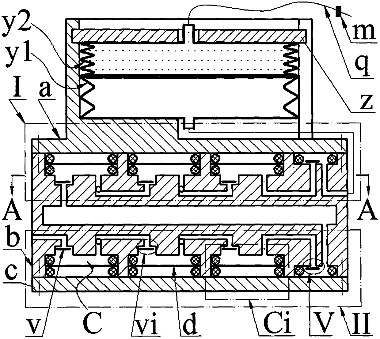
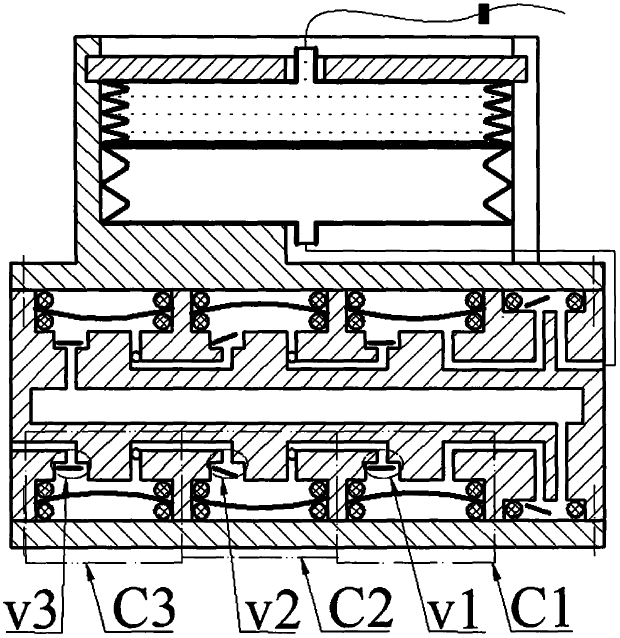
[0014] The middle part of the box b is equipped with a buffer cavity b9, the top is equipped with an upper inlet hole b1 and an upper outlet hole b6, the bottom is equipped with a lower inlet hole b1' and a lower outlet hole b6', and the upper and lower sides of the box b are equipped with outlets. b3 and at least two body cavity groups Bi, the number of body cavities b2 contained in the body cavity groups Bi from the upper inlet hole b1 to the upper outlet hole b6 and from the lower inlet hole b1' to the lower outlet hole b6' decreases in turn; each body cavity One body cavity b2 in the group Bi is provided with an inlet b4 and an air outlet b5, and the other body cavities b2 are only provided with an air outlet b8; the top of the box b includes the inlet b4 of the body cavity group Bi with the largest number of body cavities b2. The inlet hole b1 communicates with the buffer cavity b9, and the air outlet b5 of the body cavity group Bi with the least number of body cavities b2...


PUM


Abstract

The invention relates to a pneumatic infusion device, and belongs to the field of medical instruments. A box body is provided with a buffer cavity, an upper outlet hole, a lower outlet hole, an upperinlet hole and a lower inlet hole, the upper side and lower side of the box body are both provided with an outlet cavity and at least two body cavity groups, and the number of body cavities containedin the body cavity groups from the inlet holes to the outlet holes is decreased respectively in sequence; one body cavity in the body cavity groups is provided with an inlet cavity and an air outlet hole, and other body cavities are only provided with vent holes; the inlet cavity, an outlet cavity and valve plates arranged in the inlet cavity and outlet cavity form an inlet valve and an outlet valve; an upper cover and a bottom plate are arranged at the upper side and lower side of the box body, a piezoelectric actuator is in pressing connection to the interior of each body cavity through a seal ring to form a compression cavity, and the compression cavities in the same body cavity group are connected into a compression cavity group in parallel; the inlet holes, compression cavity groups,outlet cavities and outlet holes in the upper side and lower side of the box body are connected into an upper compression unit and a lower compression unit in series respectively, and the upper compression unit and the lower compression unit are connected in series through the buffer cavity; a bag cavity of the upper cover is internally provided with an air bag and a medicine bag, and the end of the bag cavity is provided with a baffle; the air bag is communicated with the upper outlet hole through an air delivery pipe, and an infusion tube of the medicine bag is provided with a needle and a flow valve.

Description

technical field [0001] The invention belongs to the field of medical equipment, and in particular relates to a pneumatic transfusion device. Background technique [0002] Injection mainly includes intravenous injection, intramuscular injection and subcutaneous injection. Intravenous injection is also called infusion drug administration. Most of the existing infusion devices are composed of infusion bottles, infusion tubes and infusion stands. This infusion mode will bring many problems in actual use: the flow rate is adjusted manually, and the flow control accuracy is not enough; the infusion bottle needs to be held high by others when the patient walks or goes to the toilet, which is inconvenient to move and the height of the infusion bottle is not high enough. Make the blood flow back; the patient or the nursing staff need to watch for a long time, if the infusion is not found in time, it may cause an accident; the liquid medicine is in contact with the air, and there is ...

Claims


Application Information

Patent Timeline
Patent Type & Authority Applications(China)
IPC IPC(8): A61M5/155A61M5/168
Inventor 张忠华柴君凌杨普雄李建平林仕杰曾平
Owner ZHEJIANG NORMAL UNIVERSITY
Why Eureka
Try Eureka